7.4 RGB LED Controller
This project makes an RGB LED change colour with the light in the room. In darkness it glows red; as the light rises the colour slides through green and blue, and under a bright light it turns white.
It brings together two things you have already built. The photoresistor circuit is exactly the one from 2.3 Photoresistor Analog Read, and the idea of setting a brightness instead of just switching a pin on and off comes from 3.2 Distance Fade LED. What is new is that one sensor reading now drives three outputs at the same time.
In this documentation you will learn:
- How to find the four legs of an RGB LED and which one is shared.
- How one analog reading can be turned into three separate brightnesses with
map(). - How PWM mixes red, green and blue into any colour in between.
- Why the colour fades smoothly instead of jumping.
Hardware required:
- 1x Soldered NULA MINI board
- 1x Breadboard
- 1x Photoresistor (LDR)
- 1x RGB LED
- 1x 10kΩ resistor
- 3x 330 Ω resistors
- 8x Jumper wires
- 1x USB-C cable
Putting the components together
Follow the twelve steps below. Each photo is taken from the same position, so you can compare it with the previous one and see exactly what changed.
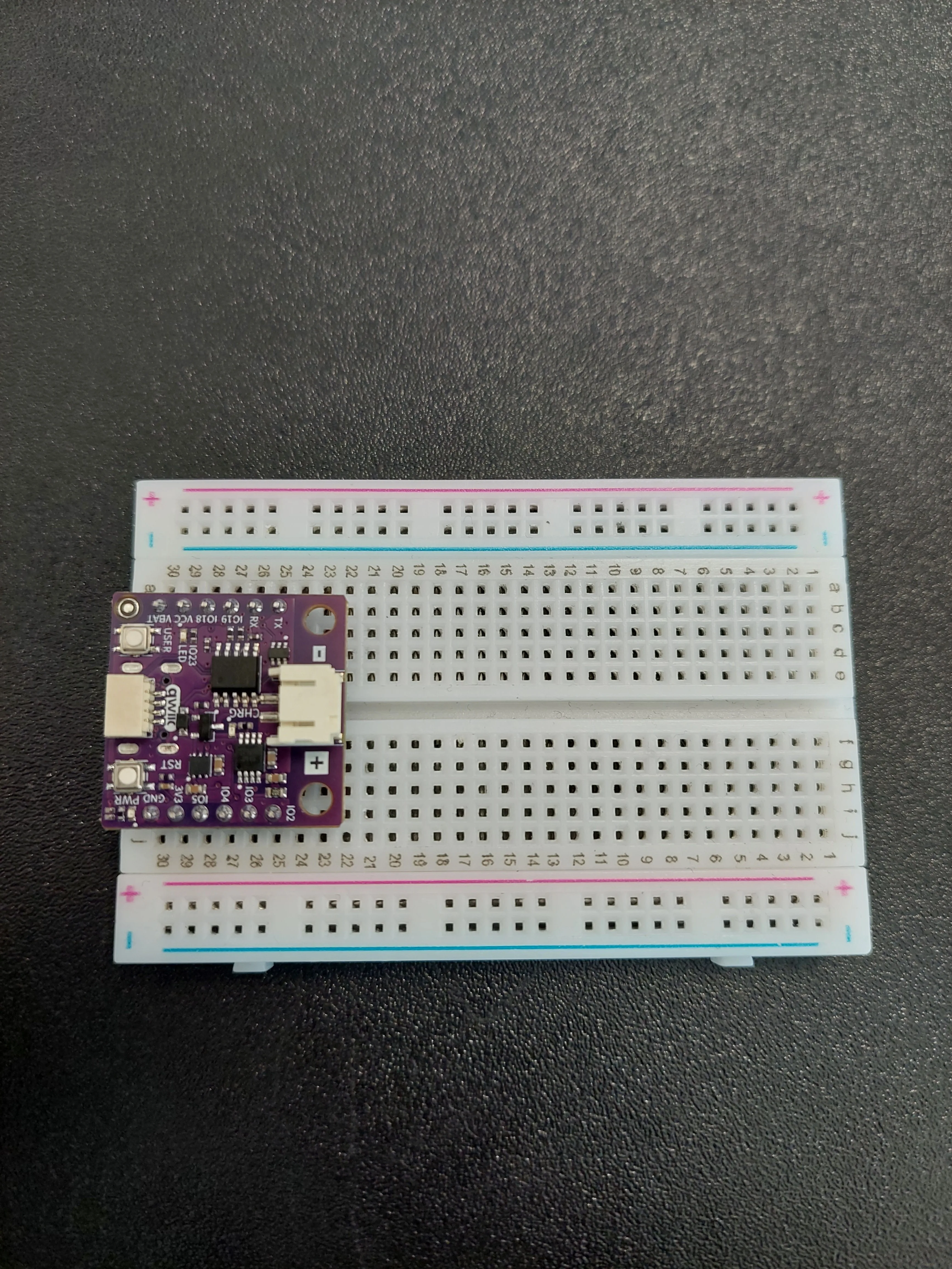
1. Insert the NULA MINI board on the breadboard
Push the board into one end of the breadboard so that its two rows of pins sit on either side of the centre channel, with the chip facing down. It should occupy rows 25 to 30.
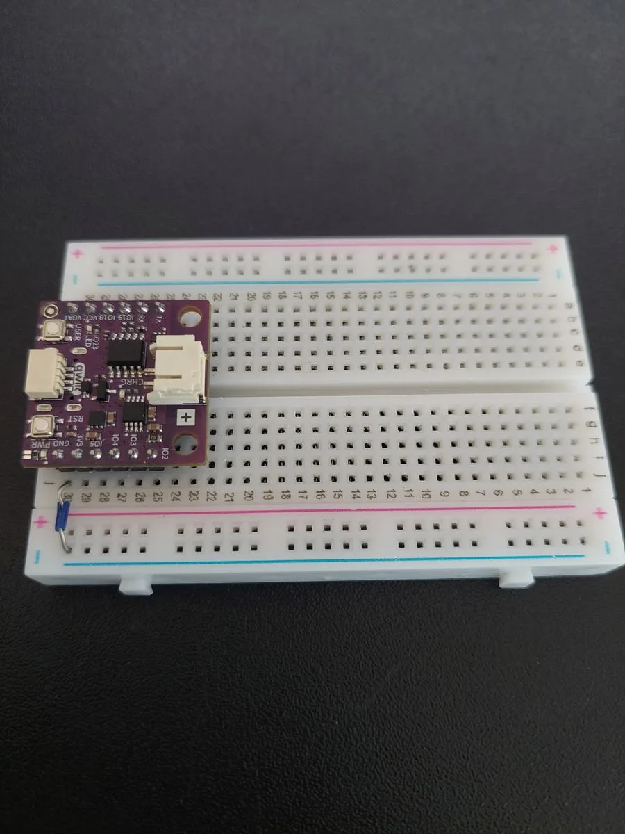
2. Bring ground out to the rail
One jumper from j30 (GND) across to the blue − rail. That rail becomes the shared ground for the whole circuit, and both halves connect back to it.
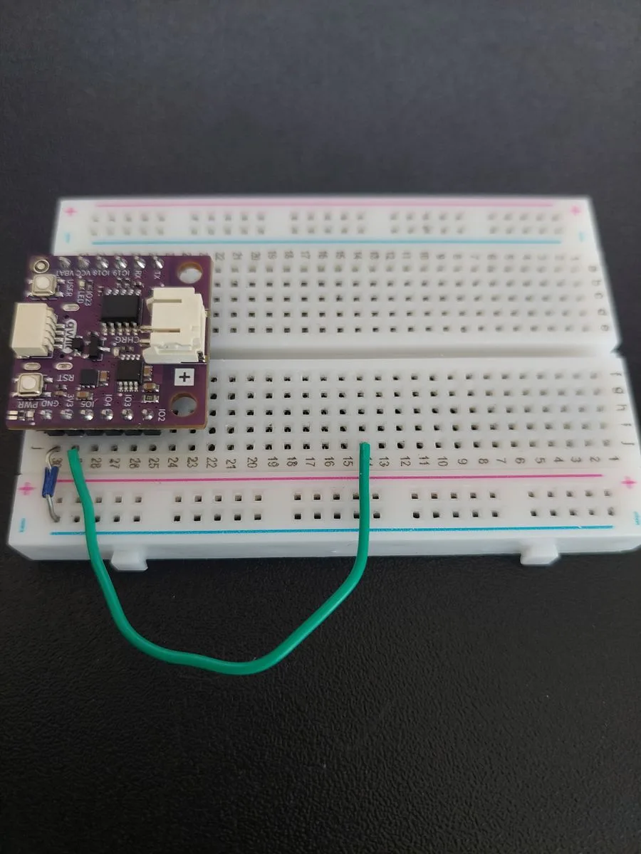
3. Bring 3.3 V out to row 14
A second jumper, from j29 (3V3) up to row 14. This is the top of the measuring circuit.
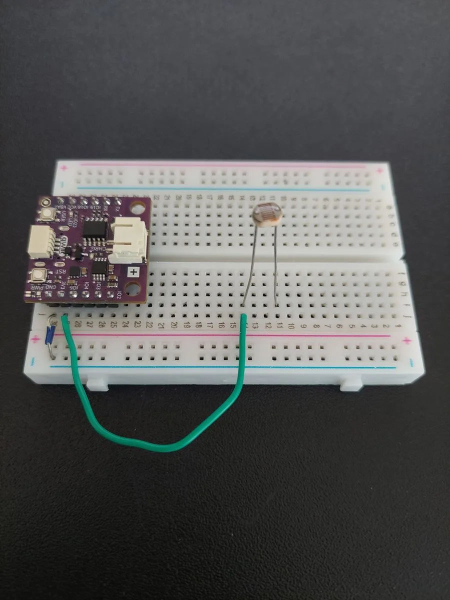
4. Add the photoresistor
The photoresistor bridges row 14, where 3.3 V now arrives, and row 11.
5. Add the 10kΩ resistor
The resistor continues the chain downwards, from row 11 to row 9.
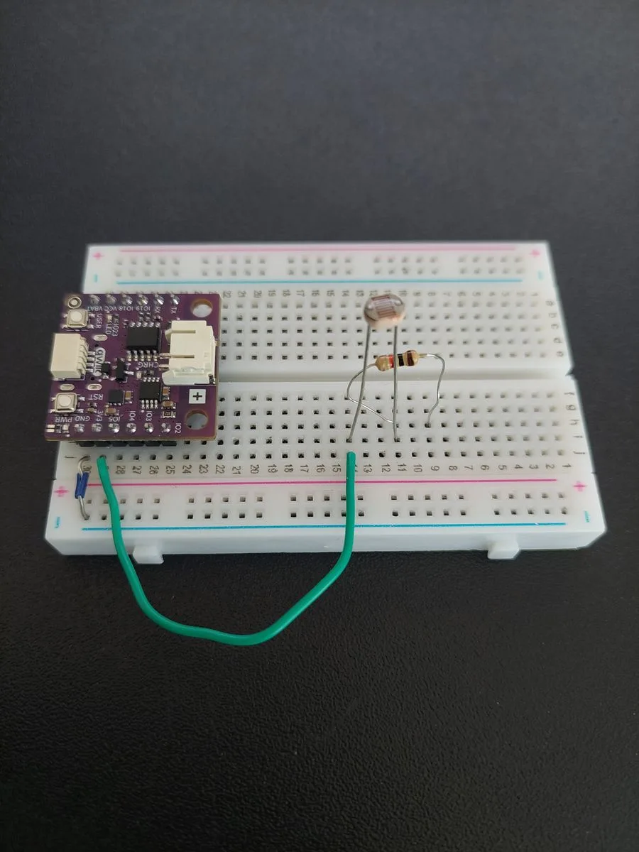
6. Connect the resistor to ground
One jumper from row 9 across to the blue − rail.
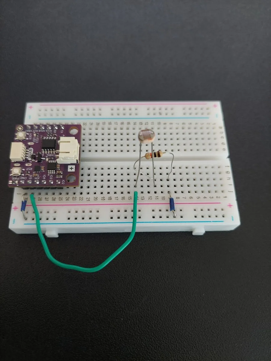
The chain is now complete: 3.3 V → photoresistor → 10kΩ → GND. Current flows through both parts in series.
7. Tap the middle with IO5
Now the measurement itself. Run a jumper from j28 (IO5) to row 11, the row shared by the photoresistor's lower leg and the resistor's upper lead.
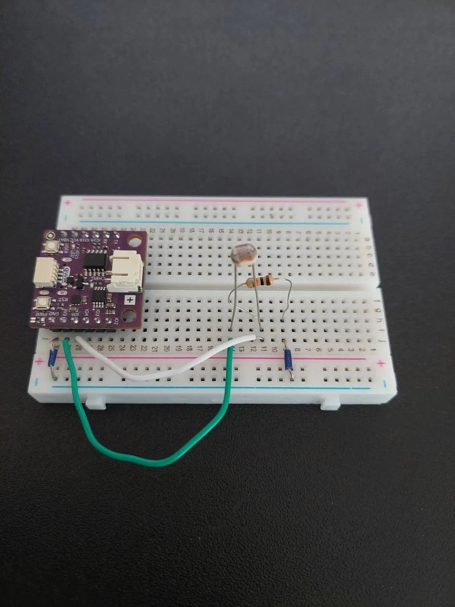
IO5 measures. If the wire lands on row 14 or row 9 instead, you will still get a reading. It simply will not change when the light does.8. Add the RGB LED
An RGB LED is three LEDs in one package sharing a single leg. Hold it with the legs pointing down and find the longest one. That is the shared leg, the common cathode. On this LED it sits third along, with one leg on one side of it and two on the other.
Seat the LED so its four legs land in rows 1, 2, 3 and 4, with the long leg in row 3:
| Leg | Row |
|---|---|
| Red, outermost, furthest from the long leg | 1 |
| Green, between Red and the long leg | 2 |
| Common cathode, the longest leg | 3 |
| Blue, alone on the other side of the long leg | 4 |
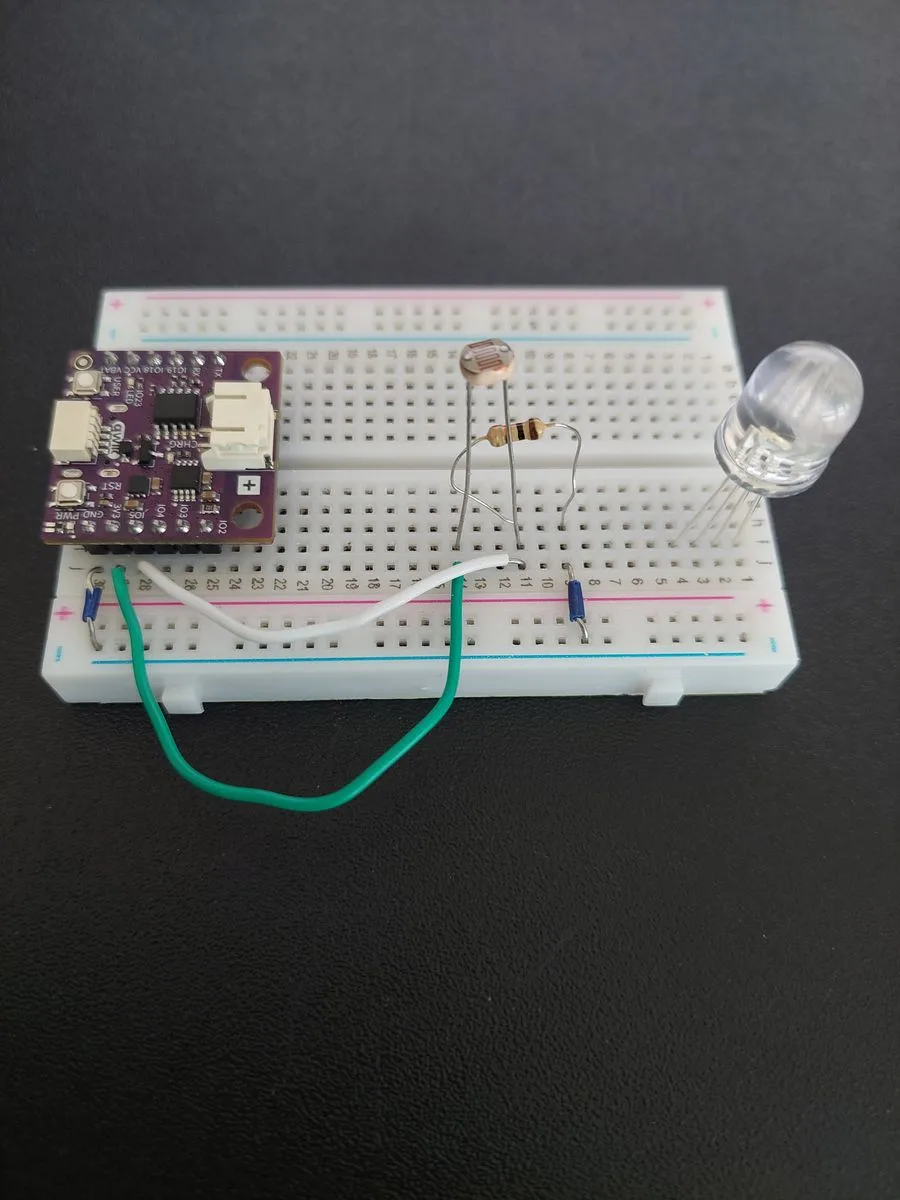
9. Ground the common cathode
One jumper from row 3 to the blue − rail. All three colour channels return to ground through this single wire.
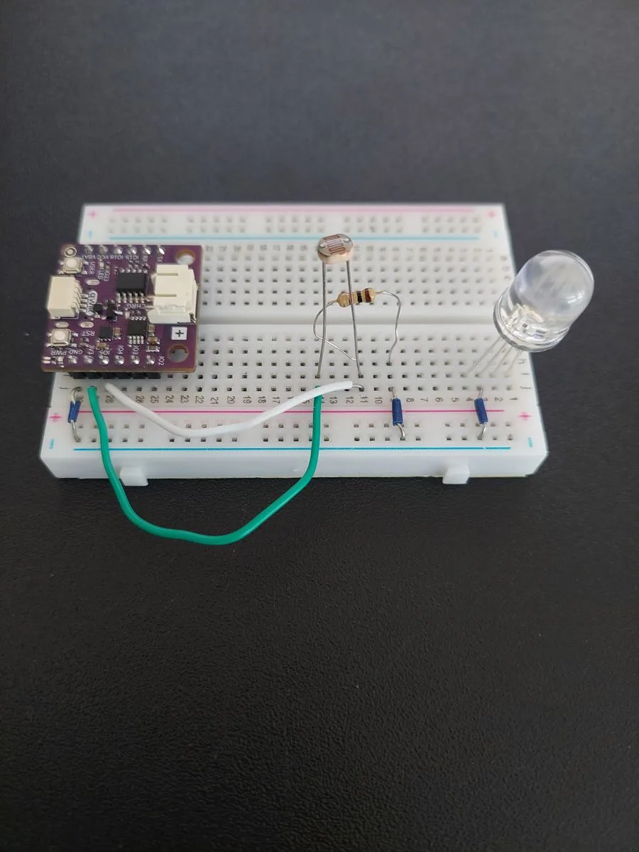
10. Add the three 330 Ω resistors
Each colour channel needs its own current limiter. Bridge each of the three colour legs out to a free row further along the board:
- from row 1 (Red) to a free row
- from row 2 (Green) to another free row
- from row 4 (Blue) to a third free row
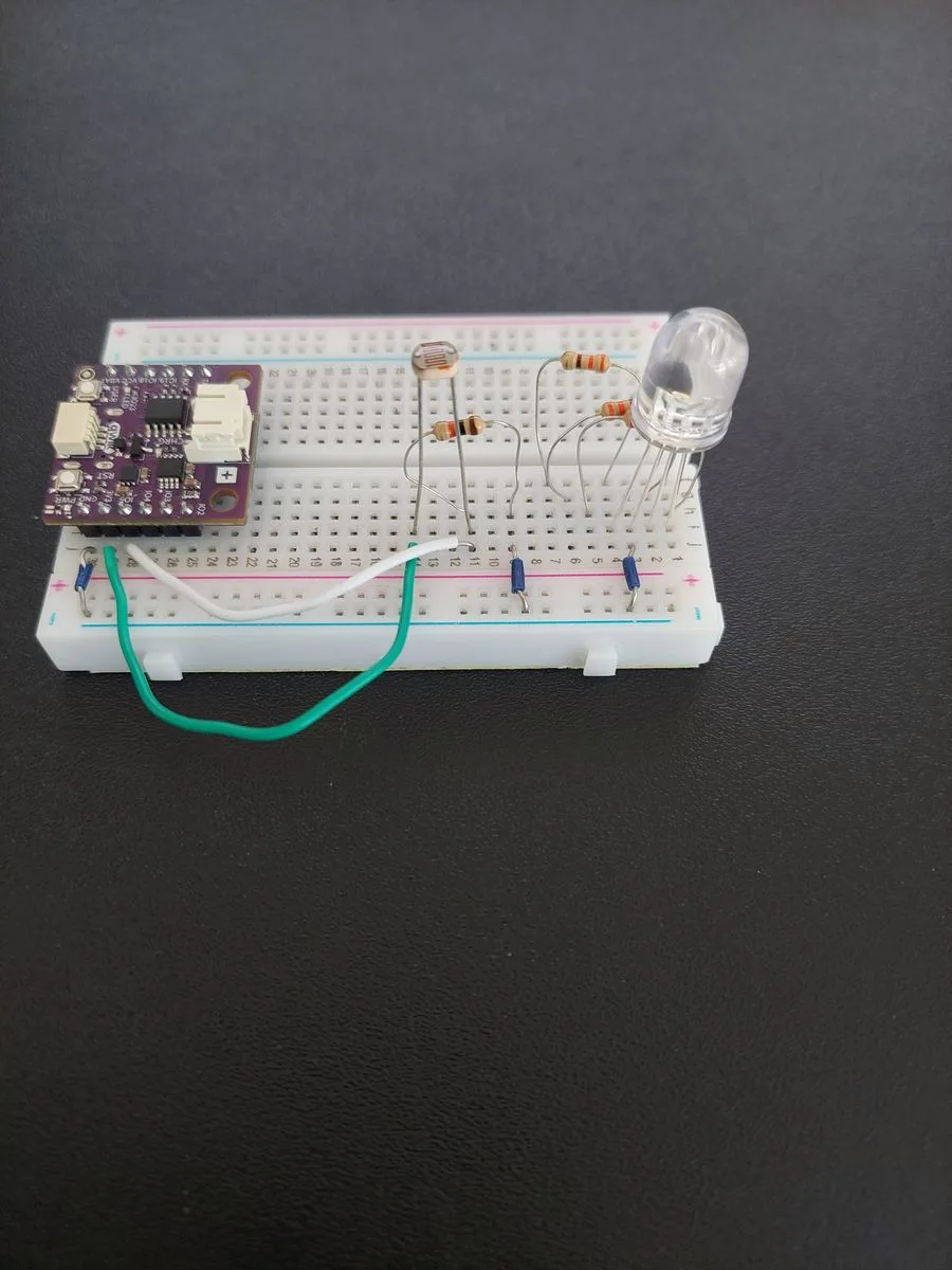
11. Wire the three colour channels to the board
Three more jumpers, from the far end of each resistor back to the matching pin. Use three different colours of wire, because they run side by side and you will want to tell them apart later.
| Channel | From | To |
|---|---|---|
| Red | the Red resistor's free row | j25 (IO2) |
| Green | the Green resistor's free row | j26 (IO3) |
| Blue | the Blue resistor's free row | j27 (IO4) |
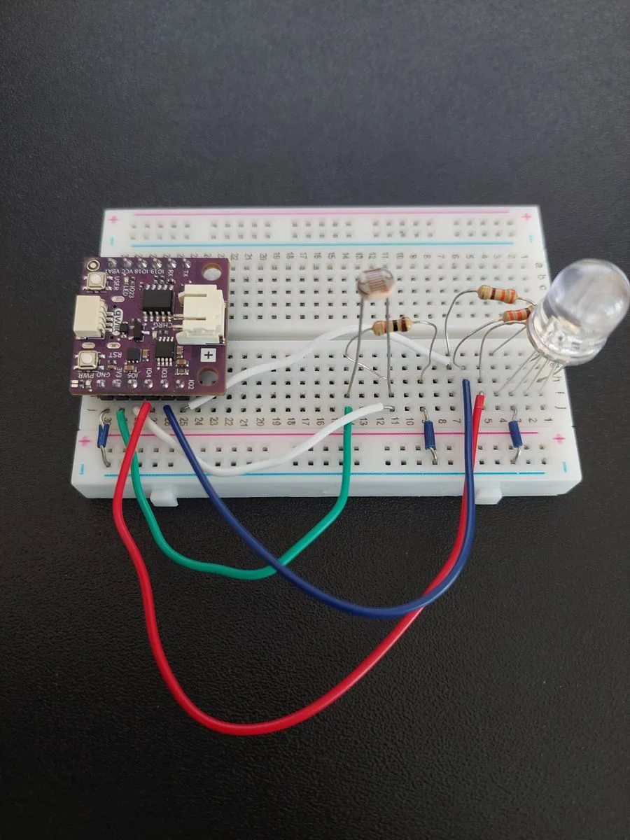
GND, 3V3, IO5, IO4, IO3, IO2) rather than guessing from the middle.12. Connect the board to your computer
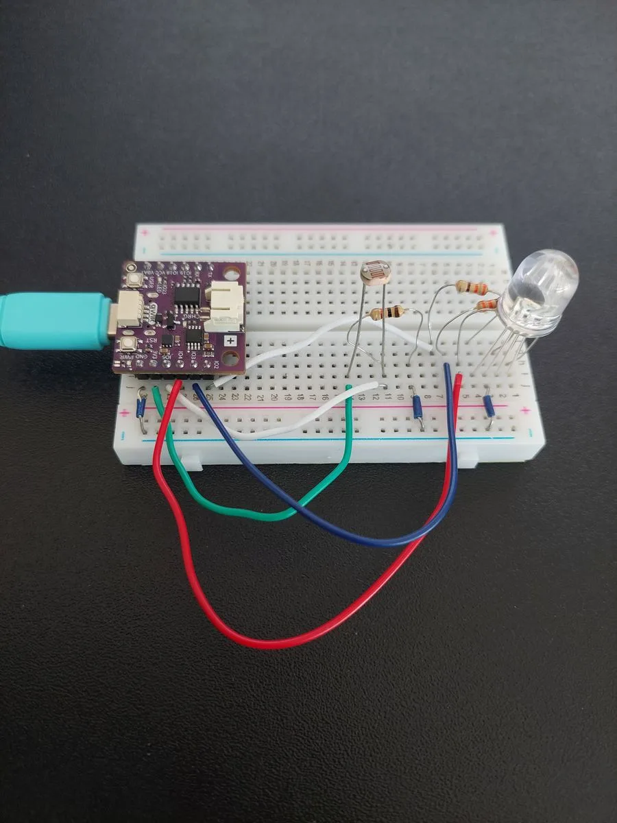
How one sensor becomes three colours
Reading the light
The board cannot measure resistance, only voltage. A photoresistor changes its resistance with light, so on its own it gives the board nothing to read. Pairing it with the fixed 10kΩ makes a voltage divider, and the voltage at the point between the two depends on the ratio of their resistances:
- In bright light the photoresistor's resistance drops, it keeps less of the 3.3 V for itself, and the reading at
IO5rises. - In darkness its resistance climbs, it keeps more of the voltage, and the reading falls.
analogRead() turns that voltage into a number from 0 to 4095, because the NULA MINI has a 12-bit ADC.
Setting the colour
analogWrite() does the opposite. Instead of only switching a pin fully on or fully off, it switches it on and off very quickly, using PWM, or Pulse Width Modulation, and the longer the pin stays on during each cycle, the brighter that channel looks. Writing all three at once is what mixes a colour.
Each channel takes a value from 0 to 255 here, which is the board's default output range. The three together are just an ordinary RGB colour: 255, 0, 0 is red, 0, 255, 0 is green, and 255, 255, 255 is white.
Joining them up
The light range is split into three equal parts. FIRST_THIRD is 1365 and SECOND_THIRD is 2730, simply 4095 divided into thirds, and each part gets its own transition:
LDR value | What the code does | Result |
|---|---|---|
| 0 → 1365 | red fades down while green fades up | red → green |
| 1366 → 2730 | green fades down while blue fades up | green → blue |
| 2731 → 4095 | blue stays full while red and green rise | blue → white |
In every part, one channel is mapped upwards while another is mapped downwards. That is what makes one colour slide into the next instead of jumping. And because each part begins exactly where the previous one ended, the boundaries are invisible: at 1365 the colour is pure green whichever side you approach it from.
Code
/**
 **************************************************
 *
 * @file        7.4_RGB_LED_Controller.ino
 * @brief       Project that uses a photoresistor to set the colour of an RGB LED. As the light in the room changes,
 *              the colour slides from red in darkness, through green and blue, all the way to white in bright light.
 *              It builds on the photoresistor from section 2.3 and the LED brightness control from section 3.2, and
 *              shows how one sensor reading can drive three outputs at the same time.
 *              For details, connection diagram and more, check out the example documentation at: <link placeholder>
 * @author      Soldered
 ***************************************************
 */

/*
This is a variable to which we pass the number of pin that we had connected the photoresistor's output to. Because we
need to read a whole range of values here and not only HIGH or LOW, this has to be a pin that supports analog input.
The NULA board has a pin naming logic as follows: IO5, where 5 is the number that we give to the variable.

This example also needs a 10k resistor. A photoresistor changes its resistance with light, but the board can only
measure a voltage, so we pair the two in what is called a voltage divider: the fixed resistor turns the changing
resistance into a changing voltage that the board can read.
*/
const int LDR_PIN = 5;

/*
These are the variables to which we pass the numbers of pins that we had connected the three colour channels of the
RGB LED to. An RGB LED is really three LEDs in one package, one red, one green and one blue, and by lighting them at
different strengths we can mix any colour we like. All three pins have to support PWM, which is what lets us set a
brightness instead of only on or off.

Remember that each of the three colour channels needs its own 330 Ohm resistor in series with it. An RGB LED counts as
three LEDs, so it takes three resistors, and without them the channels draw more current than either they or the pins
are built for.
*/
const int RED_PIN = 2;
const int GREEN_PIN = 3;
const int BLUE_PIN = 4;

/*
This variable will store the raw analog value read from the photoresistor. Since the NULA board uses a 12-bit ADC, the
value will range from 0 in complete darkness to 4095 in bright light.
*/
int ldrValue = 0;

/*
These three variables hold the brightness of each colour channel, from 0 for off to 255 for fully on.
*/
int r = 0, g = 0, b = 0;

/*
These two variables split the light range into three equal parts, which is what gives us our three colour transitions.
4095 divided by three is 1365, so the first part ends there and the second one ends at twice that. Feel free to
experiment with these values to move the colour changes to different light levels.
*/
const int FIRST_THIRD = 1365;
const int SECOND_THIRD = 2730;

void setup() {

  /*
  Serial.begin() establishes serial communication between your board and your computer via a USB cable. We use it here
  to watch both the light level and the mixed colour, which makes it much easier to understand what the code is doing.
  */
  Serial.begin(115200);

  /*
  pinMode() is a function that configures the specified pin to behave either as an input or as an output.
  The photoresistor is something we read, so it goes into INPUT mode, while the three colour channels are things we
  write to, so they go into OUTPUT mode.
  */
  pinMode(LDR_PIN, INPUT);

  /*
  analogReadResolution() defines how many bits are used for ADC readings. The NULA MINI supports 12-bit resolution,
  which means analogRead() returns values from 0 to 4095. That is the range the colour ranges below are built around,
  so we state it here rather than relying on the default.
  */
  analogReadResolution(12);

  pinMode(RED_PIN, OUTPUT);
  pinMode(GREEN_PIN, OUTPUT);
  pinMode(BLUE_PIN, OUTPUT);

  //Print out the initial message so we know that the program started successfully.
  Serial.println("RGB LED Controller with full-spectrum color mapping started");
}

void loop() {

  /*
  analogRead() reads the voltage at the given analog pin and converts it into a number. The more light falls on the
  photoresistor, the lower its resistance and the higher this number becomes.
  */
  ldrValue = analogRead(LDR_PIN);
  Serial.print("LDR value: ");
  Serial.println(ldrValue);

  /*
  This is where the colour is decided. We split the light range into three parts and give each one its own transition,
  so that the colour never jumps: it always slides from wherever it was into the next colour.
  map() is a function that takes a number from one range and rescales it into another range, and we use it here to turn
  a light level into a brightness. Notice how in each part one channel is being mapped upwards while another is mapped
  downwards, which is exactly what makes one colour fade into the next.
  */
  if (ldrValue <= FIRST_THIRD) {

    //Darkest third: fade from red (255, 0, 0) to green (0, 255, 0).
    r = map(ldrValue, 0, FIRST_THIRD, 255, 0);
    g = map(ldrValue, 0, FIRST_THIRD, 0, 255);
    b = 0;
  }
  else if (ldrValue <= SECOND_THIRD) {

    //Middle third: fade from green (0, 255, 0) to blue (0, 0, 255).
    r = 0;
    g = map(ldrValue, FIRST_THIRD + 1, SECOND_THIRD, 255, 0);
    b = map(ldrValue, FIRST_THIRD + 1, SECOND_THIRD, 0, 255);
  }
  else {

    /*
    Brightest third: fade from blue (0, 0, 255) to white (255, 255, 255). White is simply all three channels on at
    once, which is why red and green rise here while blue stays at full brightness.
    */
    r = map(ldrValue, SECOND_THIRD + 1, 4095, 0, 255);
    g = map(ldrValue, SECOND_THIRD + 1, 4095, 0, 255);
    b = 255;
  }

  /*
  analogWrite() is a function that writes an "in between" value to a pin instead of only HIGH or LOW. It does this
  using PWM, which stands for Pulse Width Modulation: the pin is switched on and off very quickly, and the longer it
  stays on during each cycle, the brighter that colour appears. Writing all three at once is what mixes the colour.
  */
  analogWrite(RED_PIN, r);
  analogWrite(GREEN_PIN, g);
  analogWrite(BLUE_PIN, b);

  //Print the mixed colour too, so we can compare it against the light level above.
  Serial.print("RGB: ");
  Serial.print(r); Serial.print(", ");
  Serial.print(g); Serial.print(", ");
  Serial.println(b);

  /*
  A short pause between readings. Keeping it small makes the colour changes look smooth.
  */
  delay(100);
}
What you should see
Upload the sketch, then open Tools → Serial Monitor and set the baud rate to 115200. Two lines appear ten times a second: the raw light reading, and the three brightnesses the code worked out from it.
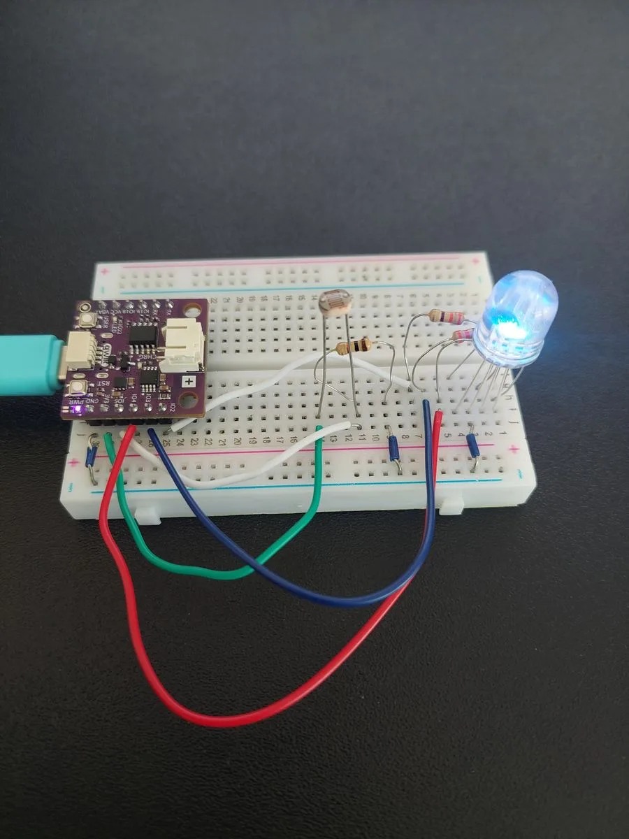
In an ordinary lit room the reading sits high, in the top third of the range, so the LED settles on a strong blue.

Now put a finger over the photoresistor. The reading drops into the middle band and the colour swings all the way to green.
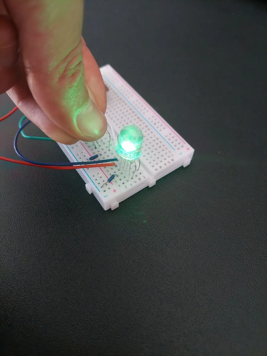

Those two captures are worth reading side by side, because you can check the code's arithmetic by hand. At 1266 the reading is in the first band, so red is mapped down from 255 and green up from 0: 255 − 1266 × 255 ÷ 1365 is 18.5, which the board rounds to the 19 it printed. The number on the screen and the colour in front of you are the same fact, twice.
The whole range
| What you do | Roughly what you will read | RGB | Colour |
|---|---|---|---|
| Leave it in a lit room | ~2900–3300 | 35, 35, 255 | blue |
| Shade it with a finger | ~1270 | 19, 236, 0 | green |
| Seal your palm over it | under ~300 | 199, 56, 0 | orange-red |
| Shine a phone torch on it | close to 4095 | 255, 255, 255 | white |
IO5 really is tapping row 11.If the colours come out wrong
If the LED lights but shows the wrong colour (green where you expect red, or one channel that never comes on), the circuit is fine and the mapping is not. Work through it in this order:
- Check the long leg is in row 3 and wired to the − rail. If the shared leg is somewhere else, the channels fight each other and mostly stay dark.
- Check each resistor spans two rows. A shorted one makes its channel far brighter than the other two, which reads as that colour taking over.
- Swap the jumpers at the board end. If red and blue are exchanged, swap the wires in
j25andj27. The Serial Monitor tells you what colour the board intended: if it prints255, 0, 0and you see blue, the two channels are crossed.
That last one is the useful habit: the RGB line is the board's own statement of what it is trying to display, so any disagreement between it and the LED in front of you is a wiring fault, not a code fault.
Full example
Check out the full example code on the link below:
7.4_RGB_LED_Controller.ino
Project that uses a photoresistor to control an RGB LED, smoothly changing colour from red to white based on ambient light intensity.