1.2 LED Blink
This example blinks an LED on and off with the Soldered NULA MINI board. It is usually the first project anyone builds with a microcontroller, because it covers the most basic idea there is: making a pin go HIGH (on) or LOW (off).
In this documentation you will learn:
- How to assign a pin to a variable for easier code management.
- How to configure a pin as an output using
pinMode(). - How to control pin states with
digitalWrite()(HIGH and LOW) - How to use
delay()to pause program execution
Hardware required:
- 1x Soldered NULA MINI board
- 1x Breadboard
- 1x LED (any color)
- 1x 330 ohm resistor
- Jumper wires
- USB-c cable
Putting the components together
Build the circuit first. Work through the steps in order, because each one depends on the one before it.
1. Insert the NULA MINI board on the breadboard
If your board has male headers soldered to its pins, push it into the breadboard. Connecting everything else is easier and tidier that way.
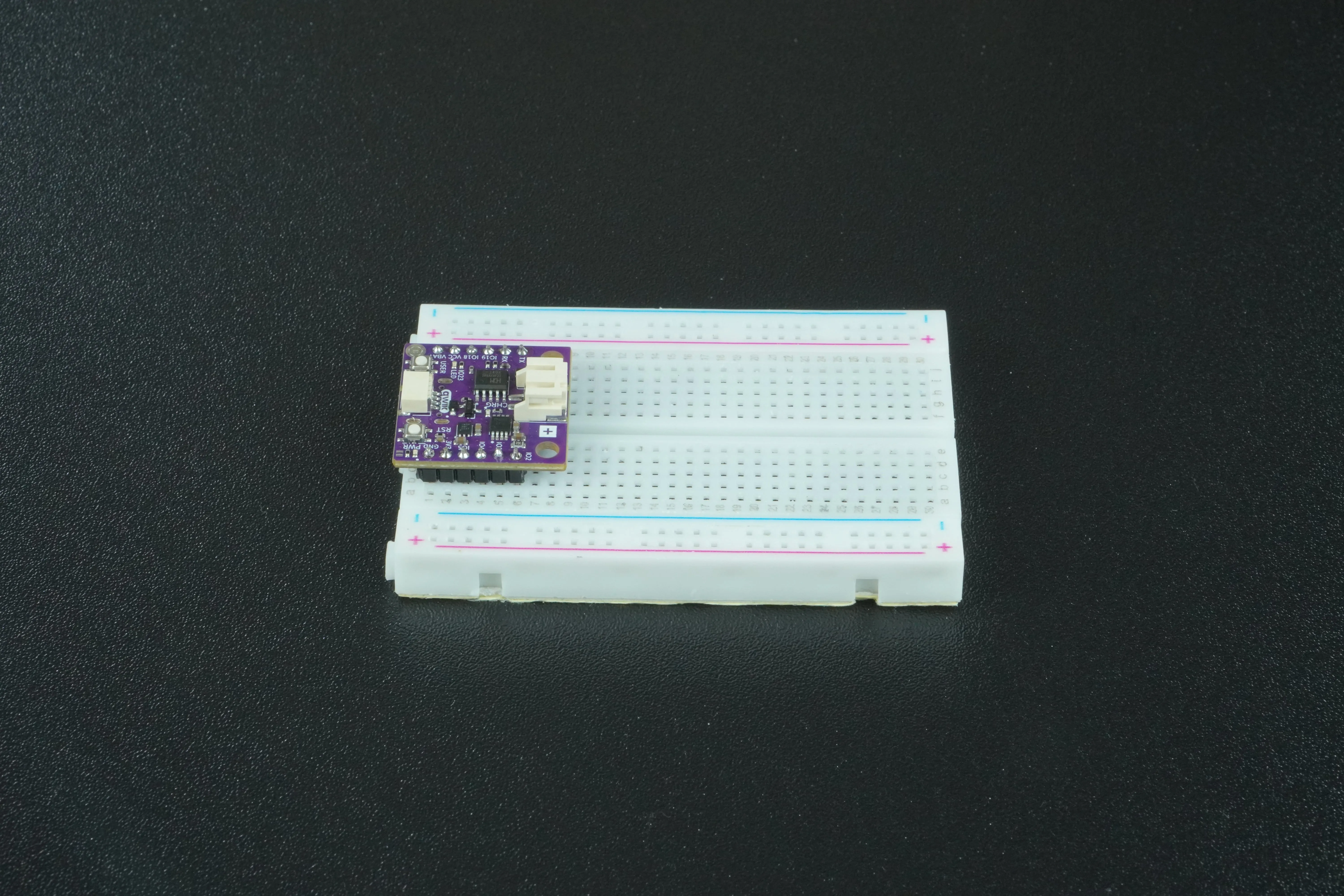
If it does not, wire the components straight to the board instead. It is messier, but it works.
2. Connect the LED to the NULA MINI board
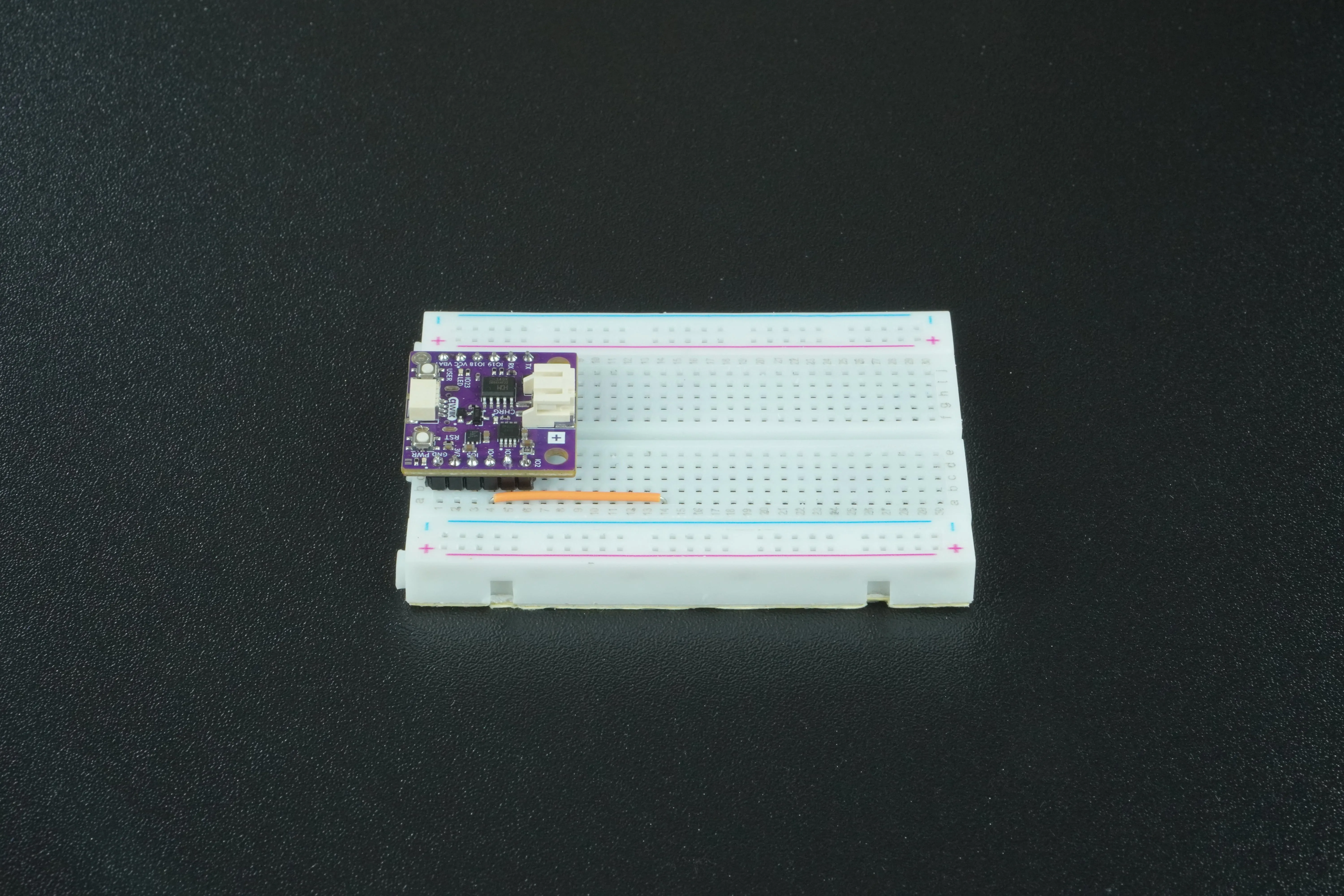
Take a jumper wire and push one end into a free GPIO pin on the board. This example uses IO4. Push the other end into any free row on the breadboard, meaning a row with nothing else in it.
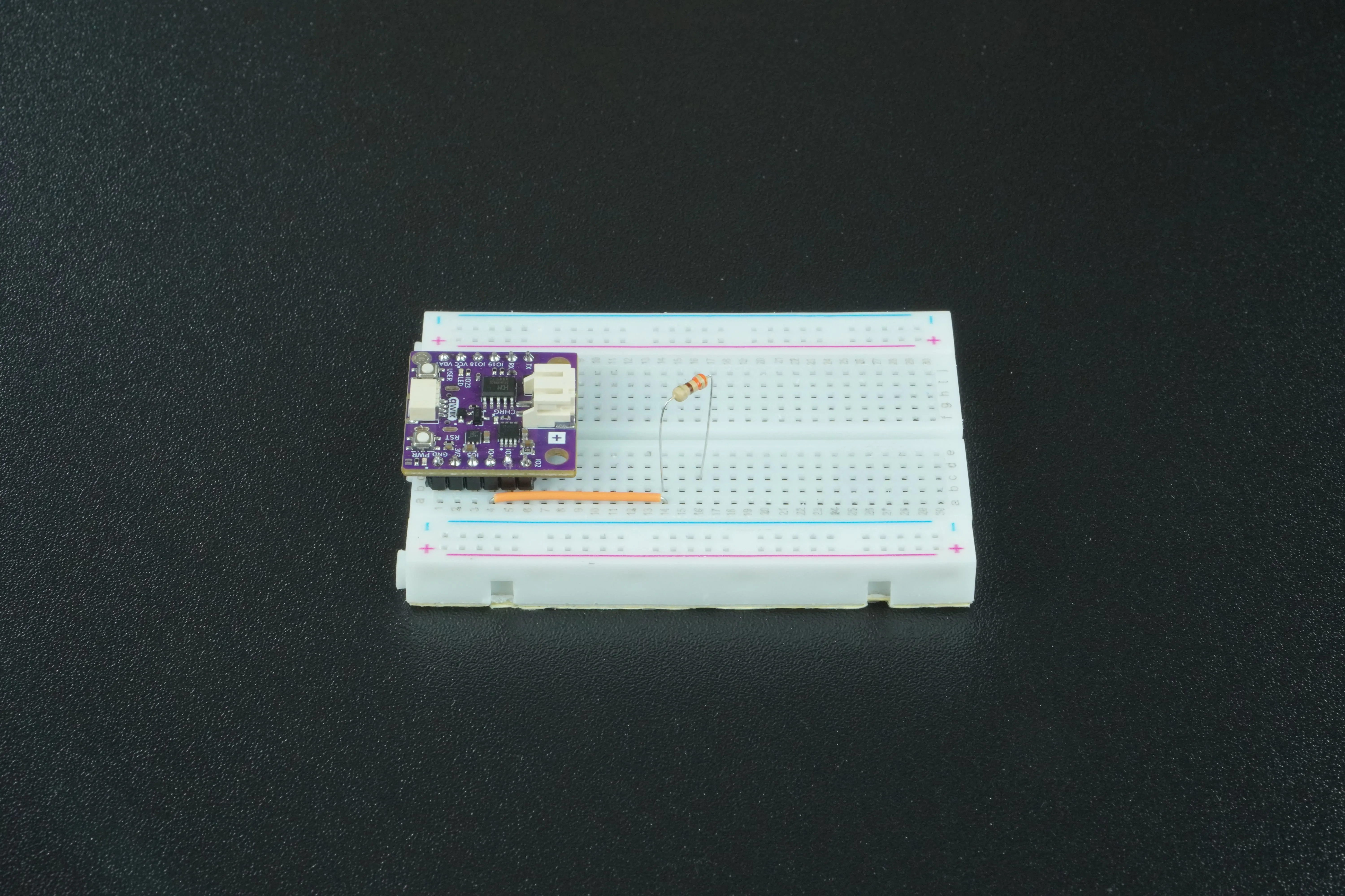
Take one 330 Ω resistor and put one end in the same row as the wire. Put the other end in a different free row.
Look at the two legs of the LED. One is longer than the other:
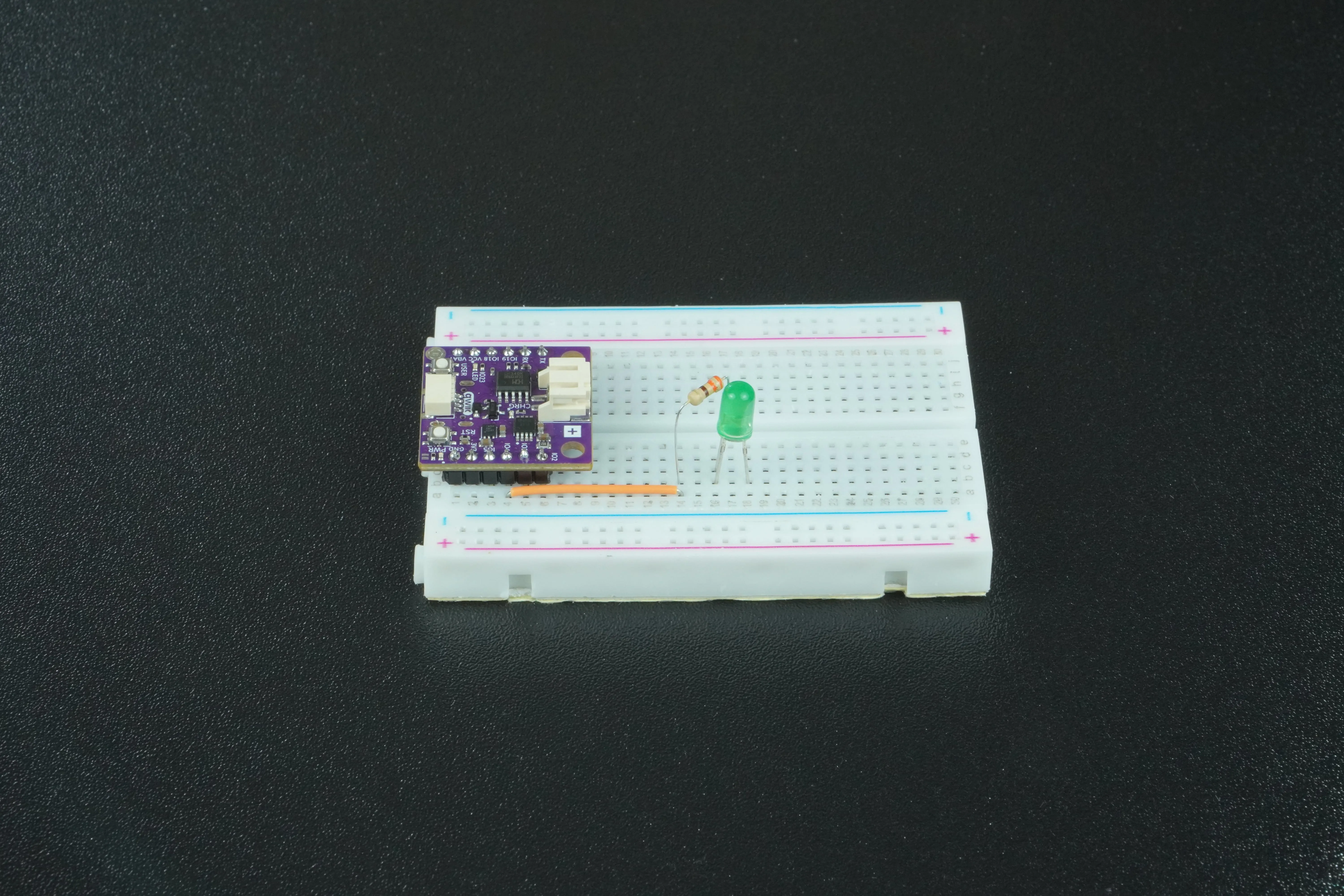
Put the longer leg, the anode, in the row holding the far end of the 330 Ω resistor.
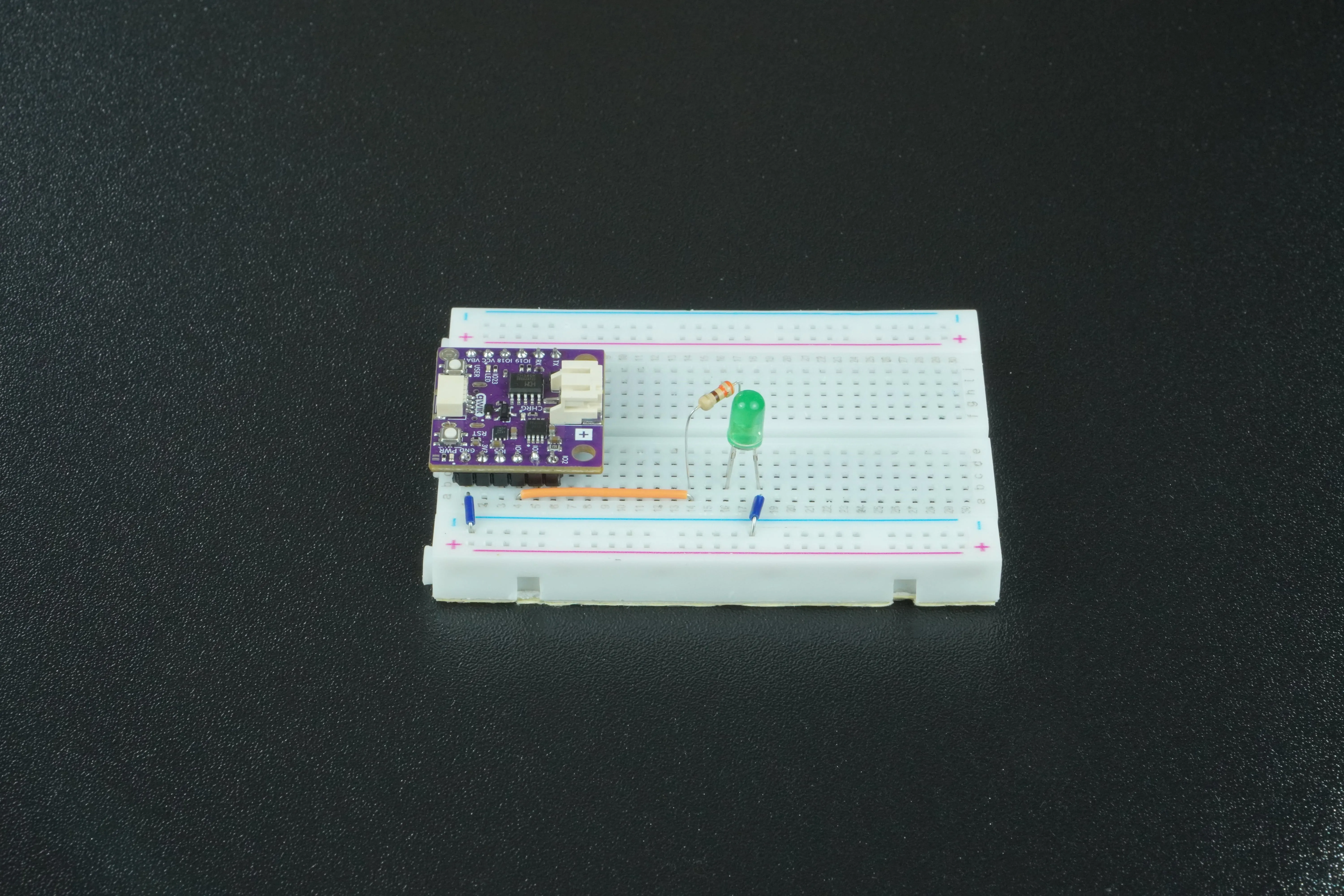
The shorter leg, the cathode, goes to the GND pin on the NULA board.
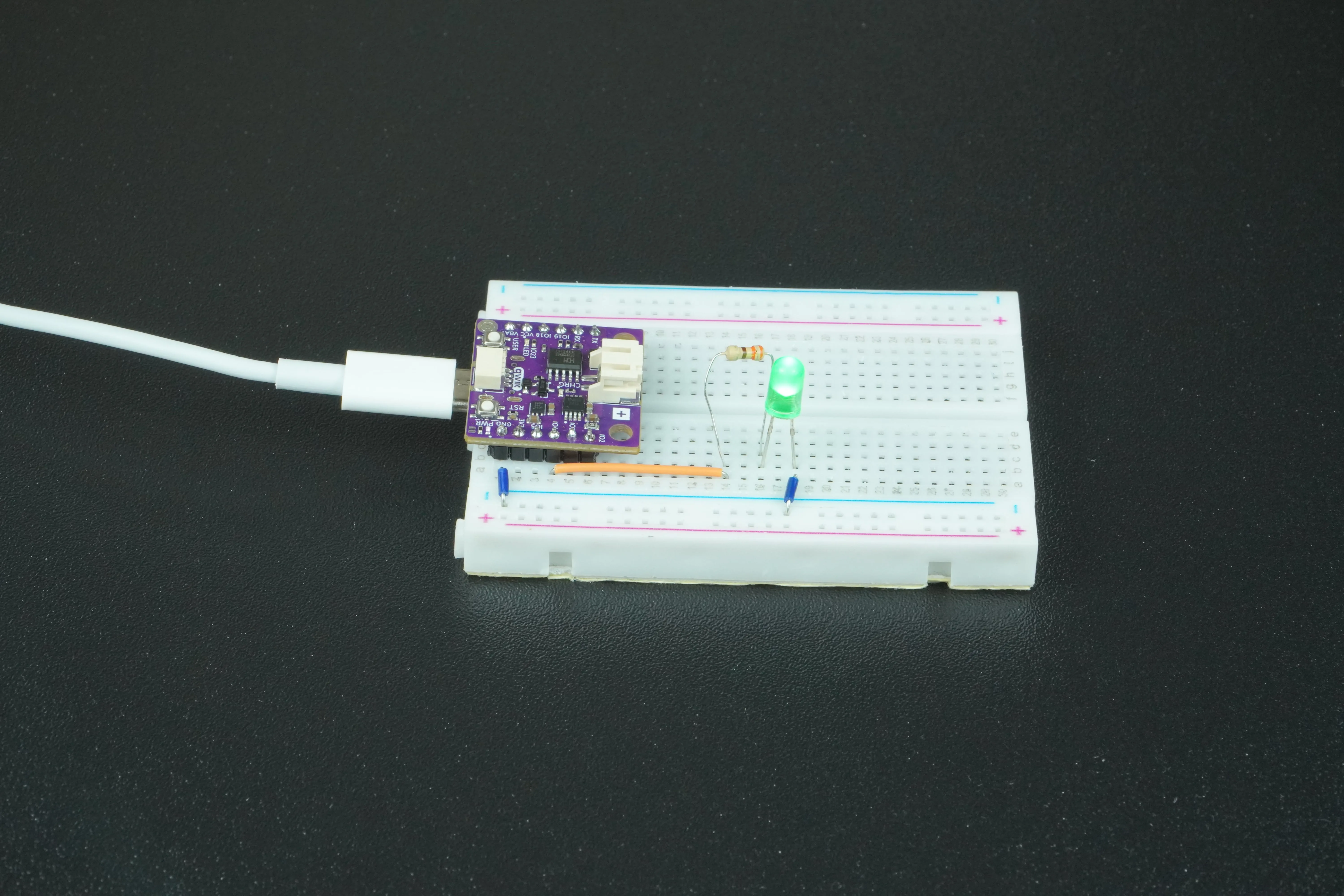
Connect the NULA MINI board to your computer via USB-c cable:
Assigning pins to variables
Instead of writing the pin number directly into every function call, you can store it in a variable for better readability. In this example, the variable pinNumber is assigned the value 4, which corresponds to the IO4 pin on the NULA board. If you decide to change the LED to another pin later, you only need to modify the variable in one place, and the rest of the code will still work.
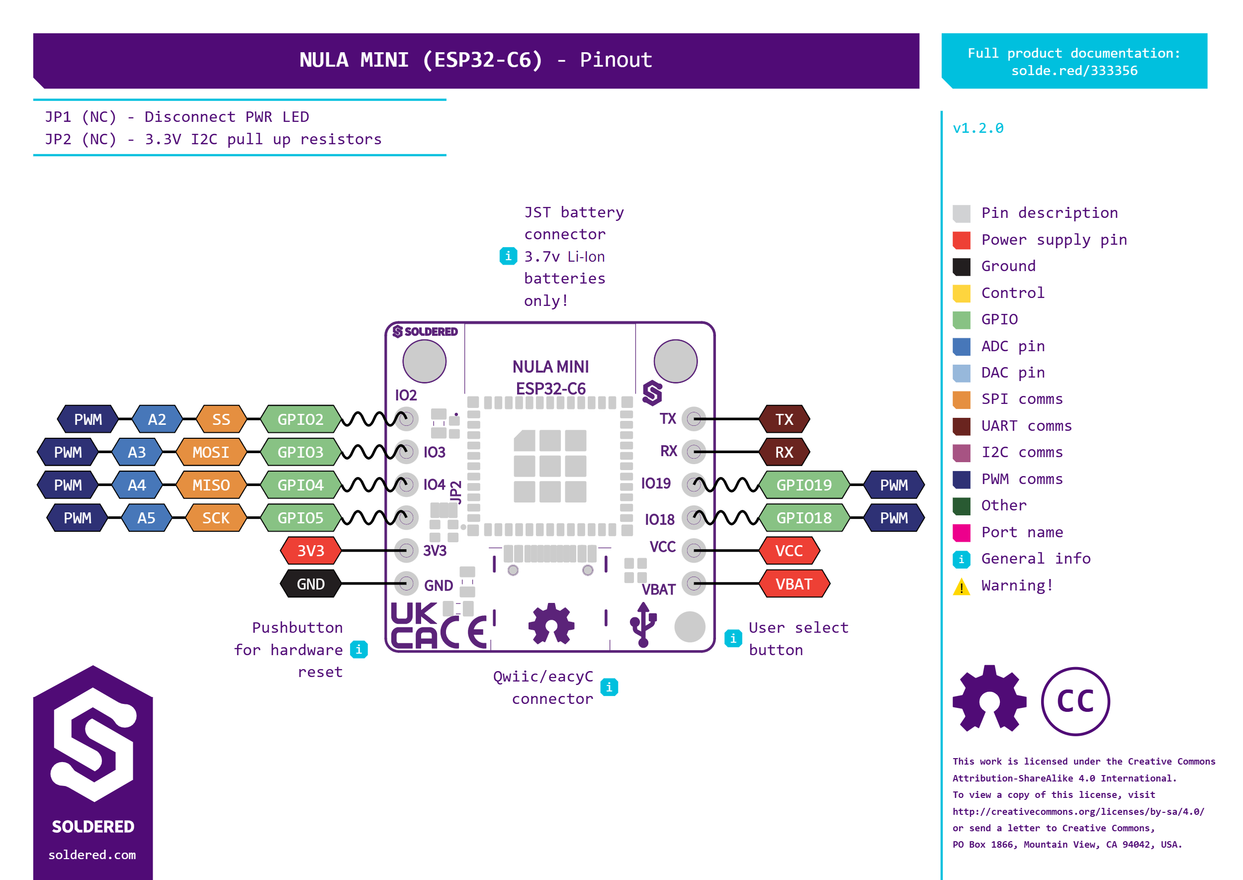
Any pin marked IO will do. The diagram below shows all of them:
We will declare variables pinNumber and delayMS before setup():
/*
This is a variable to which we pass the number of pin that we connected the LED to.
The NULA board has a pin naming logic as follows: IO4, where 4 is the number that we give to the variable.
If you wish to use a different pin, make sure you are using a IO__ marked pin.
*/
int pinNumber = 4;

/*
This is a variable that defines the blinking time, in milliseconds.
Feel free to experiment with this value.
*/
int delayMS = 1000;
Configuring pins as inputs or outputs
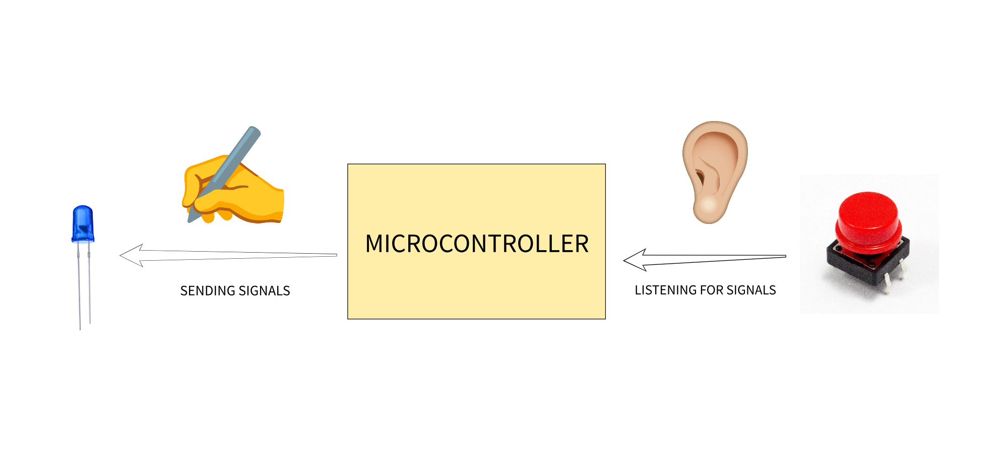
Every IO pin on the NULA MINI can work as an input (reading buttons, sensors and the like) or as an output (driving LEDs, buzzers, motors). The LED is something we want to control, so its pin has to be an output. Pins do not start out knowing which way round they work, and pinMode() is what tells them.
The function pinMode(pinNumber, mode) tells the microcontroller how a specific pin should behave. If you set the mode to OUTPUT, the pin is able to provide voltage (HIGH) or no voltage (LOW) to connected components such as LEDs, buzzers, or motors. If you set it to INPUT, the pin listens for signals coming from the outside, such as the state of a pushbutton or the level of a sensor. There is also INPUT_PULLUP, which switches on a resistor inside the chip to hold the pin at a known level when nothing is connected. There is more about this in a later chapter.
We will call the pinMode() function inside the setup():
void setup() {

  /*
  pinMode() is a function that configures the specified pin to behave either as an input or in this case as an output.
  This simply means that the pin "reads" the available data when in input mode, and "writes" data when in output mode.
  As our pin needs to turn on the LED, we will put the pin in OUTPUT mode.
  */
  pinMode(pinNumber, OUTPUT);
}
Controlling pin states with digitalWrite()
Once the pin has been configured as an output, you can control its state with the digitalWrite() function. The syntax is digitalWrite(pinNumber, value), where value can be either HIGH or LOW.
Writing HIGH sets the pin in a logic high level (3.3V on the NULA MINI board), which allows current to flow through the connected circuit, in this case, turning the LED on.
Writing LOW sets the pin to 0V, which stops the current flow and turns the LED off.
We will call the digitalWrite() function inside the loop():
void loop() {
    /*
  digitalWrite() is a function that gives us the ability to change the value that our pin (previously set as OUTPUT pin)
  writes. As the name of the function tells us, we can only switch between digital values, high and low. Those values
  are represented by different voltage levels, high is 3.3V while low is 0V. We will start with putting the pin in HIGH
  mode, giving the LED 3.3V and lighting it up.
  */
  digitalWrite(pinNumber, HIGH);
  //We put the pin in LOW mode, turning the LED off.
  digitalWrite(pinNumber, LOW);
}
Pausing program execution
If you simply turned the LED on and off in rapid succession, the changes would happen so quickly that your eyes would not detect them. To make the blinking visible, you will use the delay() function. The syntax is delay(milliseconds), where the number represents how long the program should pause.
In this example, the variable delayMS is set to 1000, which means each delay lasts one second. The code first turns the LED on with digitalWrite(pinNumber, HIGH), then pauses with delay(delayMS). After that, it turns the LED off with digitalWrite(pinNumber, LOW) and pauses again for one second. This loop continues forever, producing a visible blinking pattern.
We call delay() function after every digitalWrite() call:
void loop() {

  /*
  digitalWrite() is a function that gives us the ability to change the value that our pin (previously set as OUTPUT pin)
  writes. As the name of the function tells us, we can only switch between digital values, high and low. Those values
  are represented by different voltage levels, high is 3.3V while low is 0V. We will start with putting the pin in HIGH
  mode, giving the LED 3.3V and lighting it up.
  */
  digitalWrite(pinNumber, HIGH);

  /*
  delay() is a function that starts a pause in the code. Duration of the pause is defined with the ms parameter.
  In this case, we want to wait for a bit after we turned on the LED.
  */
  delay(delayMS);

  //We put the pin in LOW mode, turning the LED off.
  digitalWrite(pinNumber, LOW);

  //Leave the LED turned off for a bit.
  delay(delayMS);
}
Full example
Check out the full example code on the link below:
1.2_LED_blinking.ino
Example that shows how to control the blinking of a simple LED