2.1 Button Counter
So far the board has only been talking. In this example it starts listening: you will read a push button with the Soldered NULA MINI board and count how many times it has been pressed, printing the running total to the Serial Monitor.
In this documentation you will learn:
- How to wire a button with no extra components, using the resistor built into the chip
- How to configure a pin as an input with
pinMode()andINPUT_PULLUP - How to read that pin with
digitalRead() - Why a pressed button reads LOW rather than HIGH
Hardware required:
- 1x Soldered NULA MINI board
- 1x Breadboard
- 1x Push button
- 2x Jumper wires
- 1x USB-C cable
Putting the components together
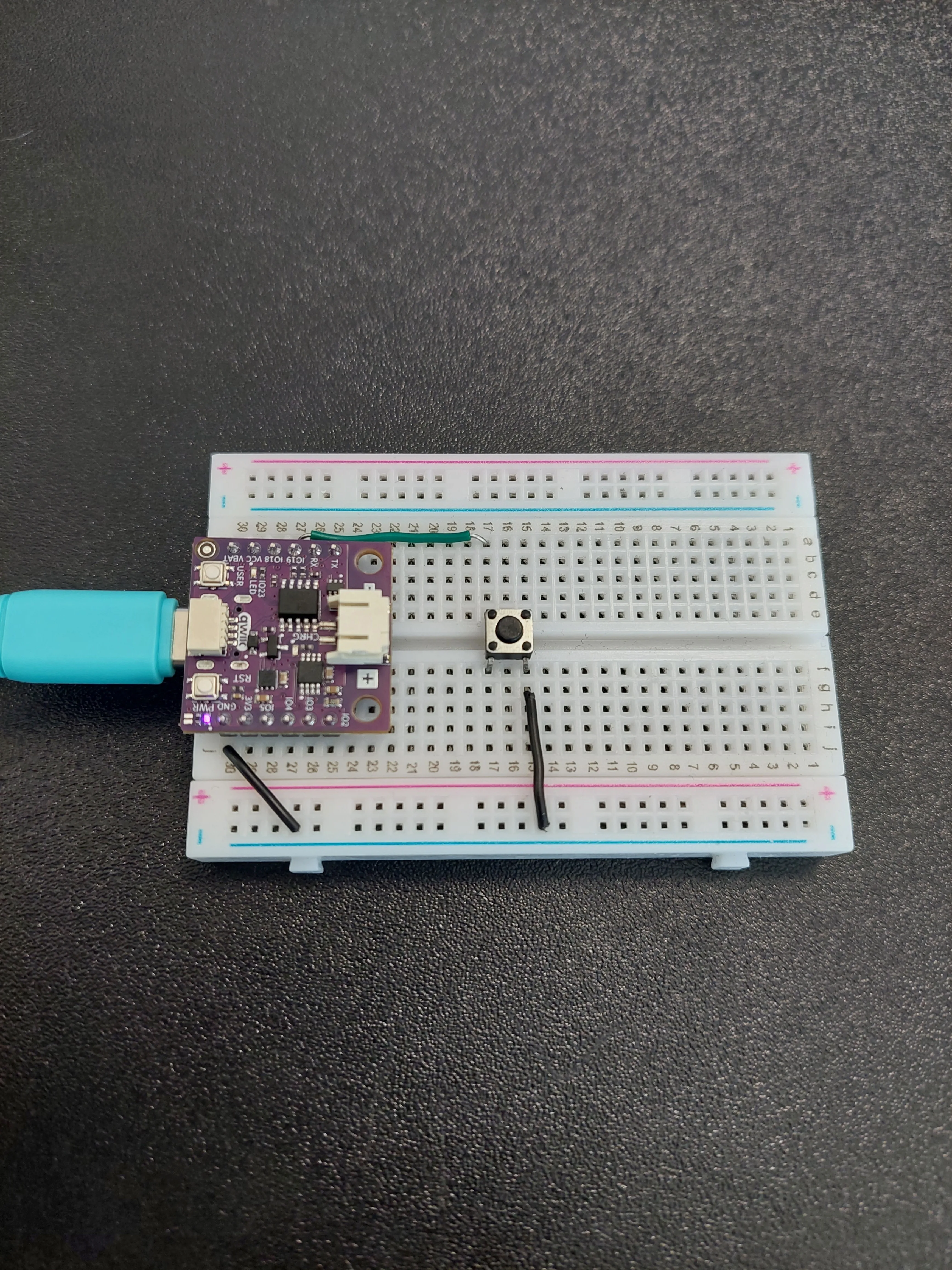
Follow the five steps below. Each photo is taken from the same position, so you can compare it with the previous one and see exactly what changed.
1. Insert the NULA MINI board on the breadboard
Push the board into one end of the breadboard so that its two rows of pins sit on either side of the centre channel, with the chip facing down. Press it in evenly until all the pins are seated.
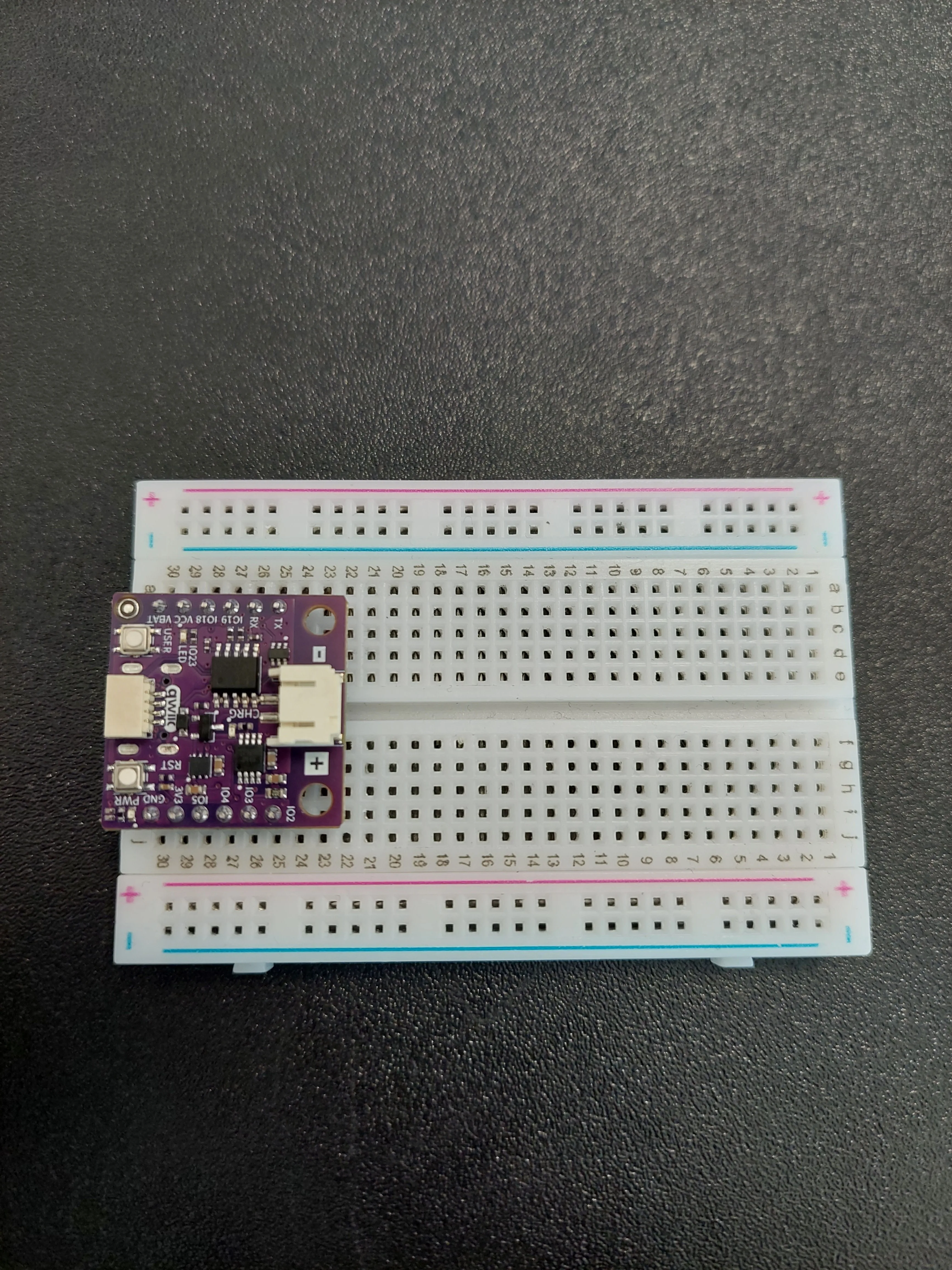
Take a moment to find the two pins this example uses. The pin names are printed along both edges of the board, and each pin sits in its own numbered row. In the photo above the board occupies rows 25 to 30, which puts IO19 in row 27 and GND in row 30.
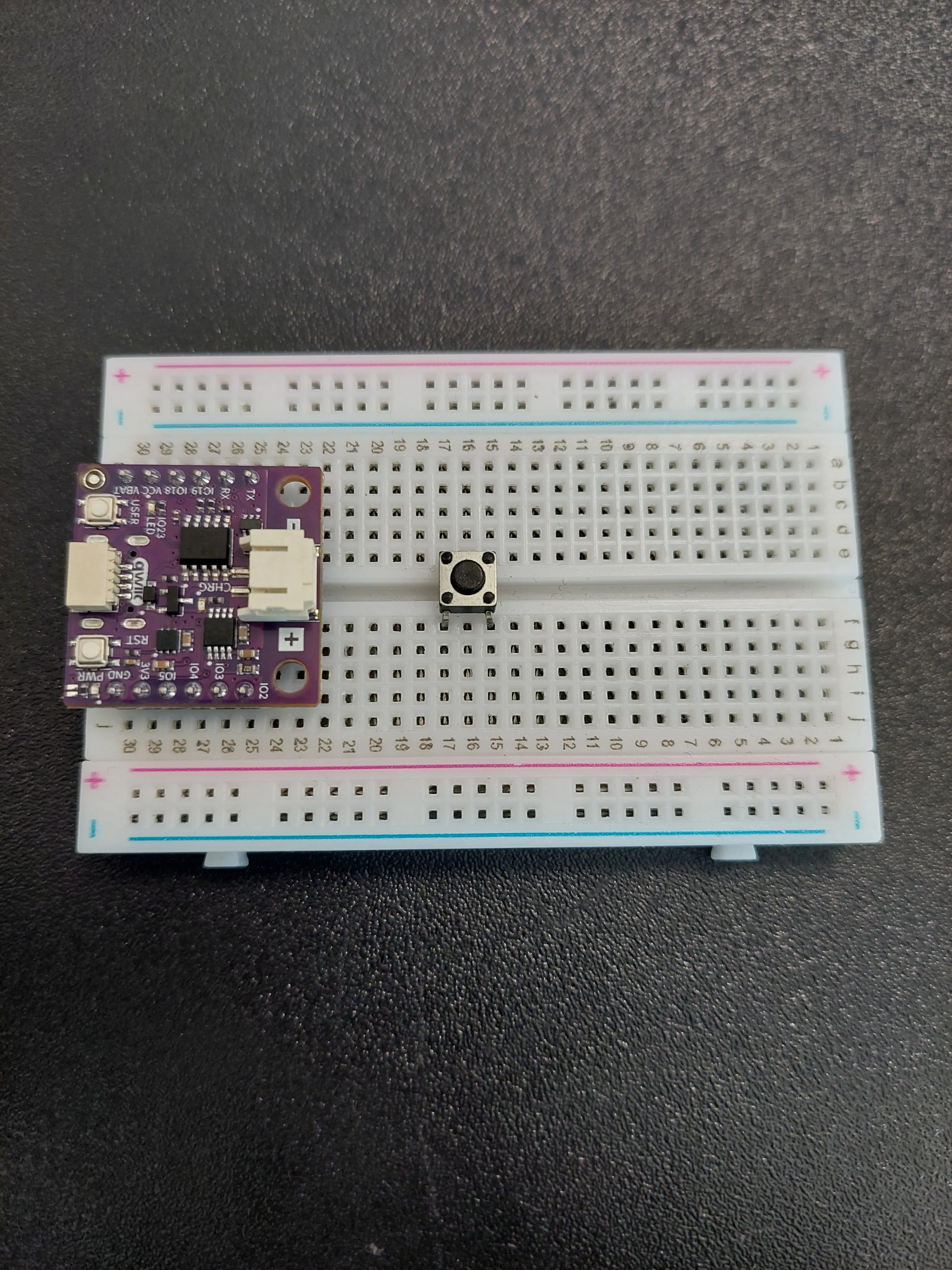
2. Place the push button
Push the button into the middle of the breadboard so that it straddles the centre channel, a few rows clear of the board. In the photo its legs are in rows 15 and 17.
3. Connect GND to the button
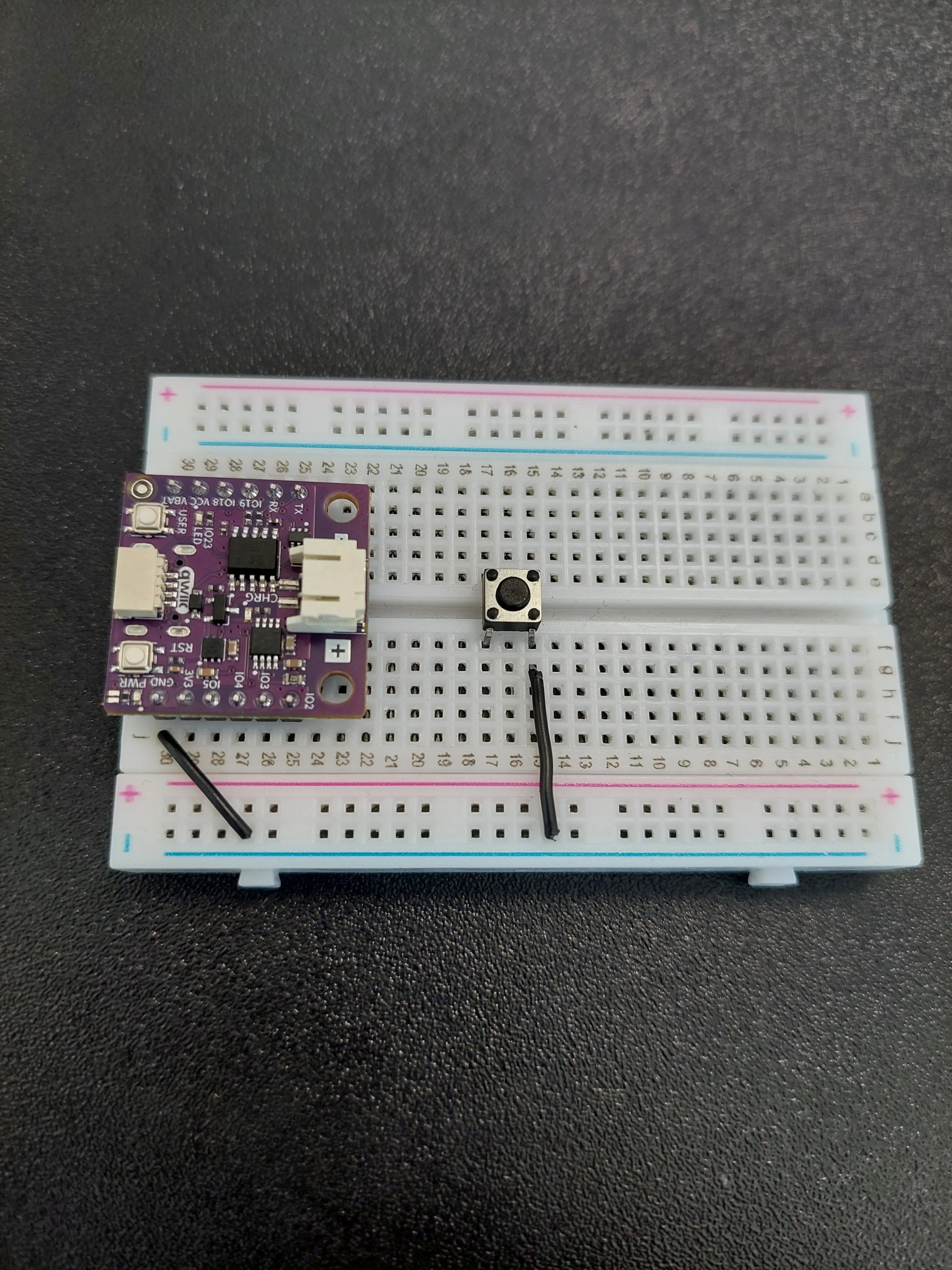
Ground goes across in two hops, using the blue − rail along the edge of the breadboard as a shared ground line.
- First jumper: from the row holding GND (row 30 in the photo) out to the blue − rail.
- Second jumper: from that same blue − rail back to row 15, on the f–j side of the button.
4. Connect IO19 to the button
Now the signal wire. Run a single jumper from the row holding IO19 (row 27 in the photo) to row 17, on the a–e side of the button.
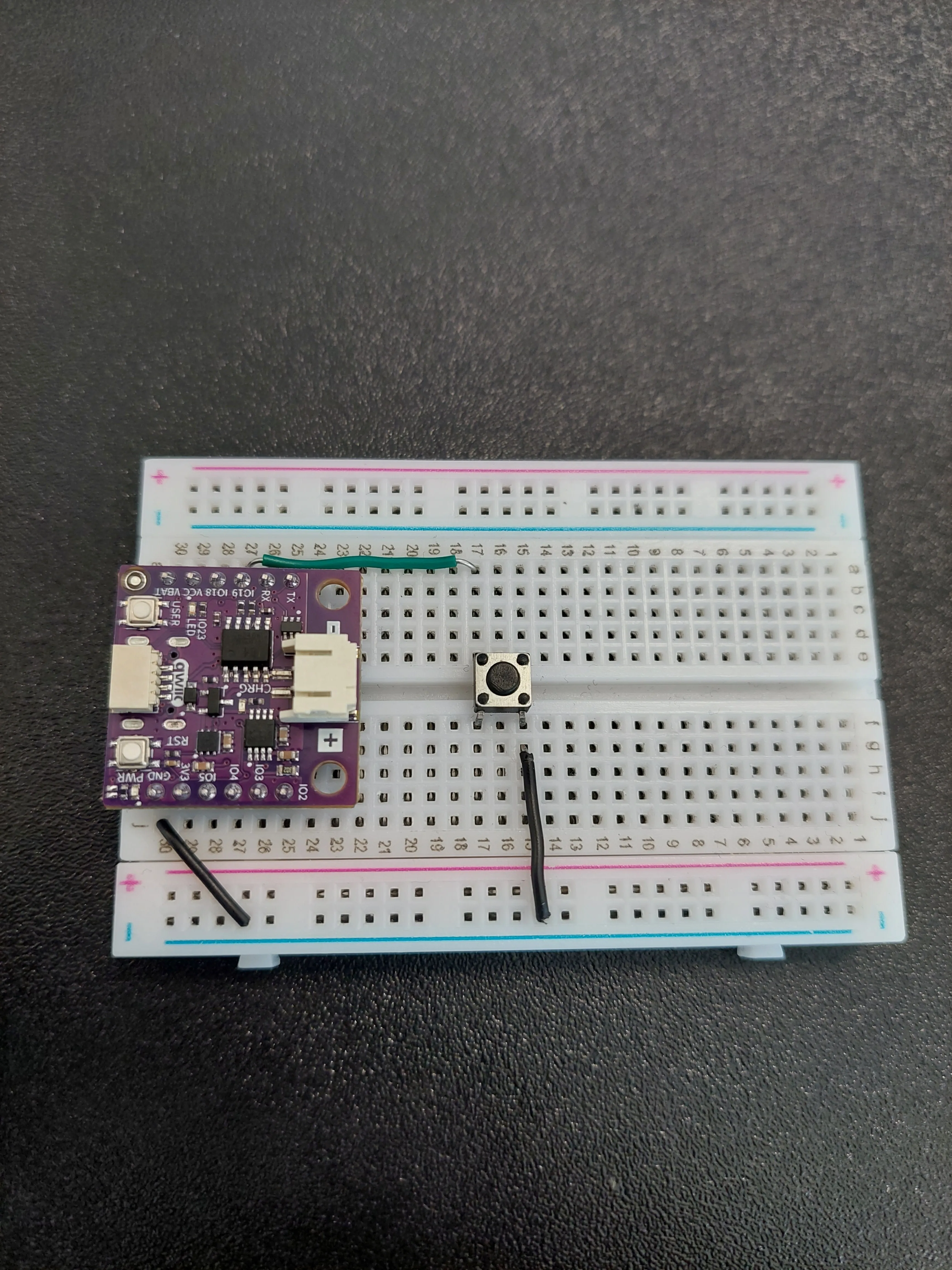
Notice that the two wires reach the button from opposite sides: row 15 on the f–j side, row 17 on the a–e side. That is the diagonal pair described above, and it is what makes the button actually switch something.
5. Connect the board to your computer
Plug the USB-C cable into the board. The power LED lights up as soon as it has power.
Reading an input
An output pin is one the board drives; an input pin is one it measures. digitalRead() reports what it finds as either HIGH or LOW.
A pin that is connected to nothing at all is a problem: it is said to be floating, and it picks up enough electrical noise from its surroundings to flip between HIGH and LOW on its own. The board would count presses that never happened. The pin needs something holding it at a known value whenever the button is not doing anything.
That is what INPUT_PULLUP is for. It switches on a resistor inside the chip that gently ties the pin to 3.3 V, so the pin reads HIGH while nothing else is going on. The button's only job is to connect that pin to GND, which overrules the weak internal resistor and drags the pin down to 0 V.
Code
/*
This is a variable to which we pass the number of the pin that we connected the BUTTON to.
The NULA board has a pin naming logic as follows: IO19, where 19 is the number that we give to the variable.
*/
const int BUTTON_PIN = 19;

/*
This variable holds the value of our counter.
Each time the button is pressed, the counter value will increase by one.
*/
int counter = 0;

void setup() {

  /*
  pinMode() is a function that configures the specified pin to behave either as an input or an output.
  As our pin needs to detect if the button has been pressed, we will put the pin in INPUT_PULLUP mode.
  INPUT_PULLUP switches on a small resistor inside the chip that gently ties the pin to 3.3V. Without it the pin would
  be floating, meaning it is connected to nothing and picks up random noise, and the board would read presses that
  never happened. Because the resistor holds the pin high, the button only has to connect the pin to GND, so no extra
  parts are needed on the breadboard.
  */
  pinMode(BUTTON_PIN, INPUT_PULLUP);

  /*
  Serial.begin() initializes serial communication between the NULA board and the computer.
  We use it here so we can print out the current counter value on the Serial Monitor.
  */
  Serial.begin(115200);

  /*
  Print out the initial message so we know that the program started successfully.
  */
  Serial.println("Button Counter Example started!");
  Serial.println("Press the button to increase the counter...");
}

void loop() {

  /*
  digitalRead() is a function that reads the value from a specified digital pin, either HIGH or LOW.
  Note that the reading is the other way around from what you might expect. The pull-up resistor holds the pin at 3.3V
  while the button is released, so the board reads HIGH, and pressing the button connects the pin to GND so it reads
  LOW. A button wired this way is called active low.
  */
  bool reading = digitalRead(BUTTON_PIN);

  /*
  If the button is pressed, increase the counter by one and print it to the Serial Monitor.
  Since this version does not include debouncing, multiple counts may appear for a single press.
  */
  if (reading == LOW) {
    counter++;
    Serial.print("Counter: ");
    Serial.println(counter);

    /*
    Wait for the button to be released before allowing another count.
    This prevents the counter from increasing too quickly while the button is still held down.
    */
    while (digitalRead(BUTTON_PIN) == LOW) {
      // Wait until the button is released
    }
  }
}
What you should see
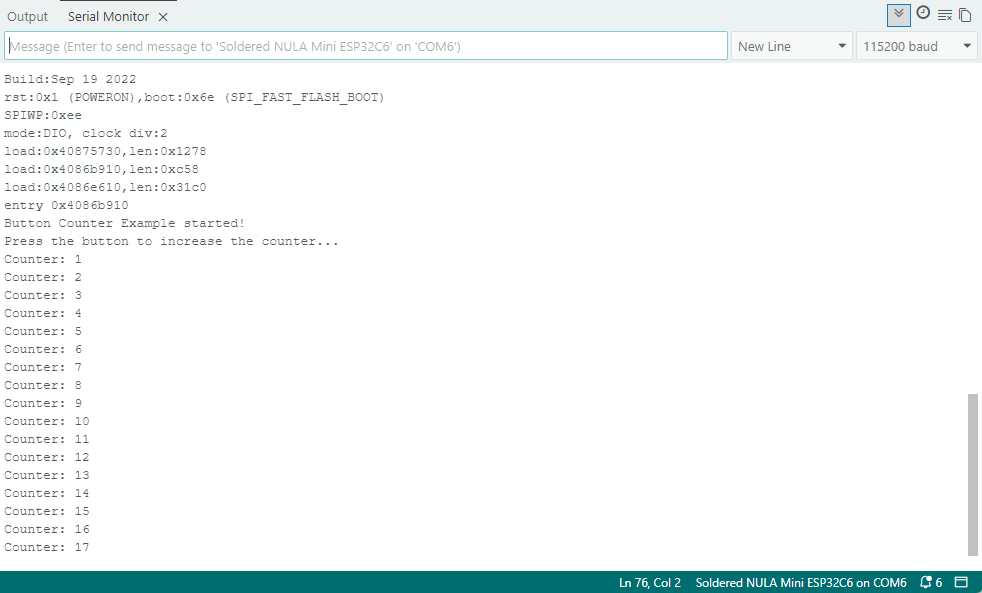
Upload the sketch, then open Tools → Serial Monitor and set the baud rate to 115200. The two opening messages appear, and every press adds a line.
Full example
Check out the full example code on the link below:
2.1_Button_Counter.ino
Example that counts how many times a button has been pressed and prints the total over Serial.