6.2 Wi-Fi LED Control
In 6.1 Connecting and Getting Data the board did the asking: it joined your Wi-Fi network, requested a page from a website and printed the answer. This example turns that around. The board is now the one being asked. It becomes a small web server of its own, and a page you open in your phone or your computer switches a real LED on and off.
Nothing about the LED itself is new. It is the same LED, the same 330 Ω resistor and the same digitalWrite() you have used since 1.1 LED Blink. What is new is where the instruction comes from. Instead of being written into the sketch ahead of time, it arrives over the network the moment somebody presses a button.
In this documentation you will learn:
- The difference between a client and a server, and why this example is the opposite of 6.1.
- What a handler is, and how
server.on()connects a web address to a function in your sketch. - How mDNS gives the board a name, so you can type
nulamini.localinstead of a row of numbers. - Why
server.handleClient()has to keep running inloop(), and what breaks if it stops. - How a few lines of JavaScript inside the page keep the status line up to date on their own.
Hardware required:
- 1x Soldered NULA MINI board
- 1x Breadboard
- 1x LED (any colour)
- 1x 330 Ω resistor
- 3x Jumper wires
- 1x USB-C cable
- A Wi-Fi network, and a phone or computer joined to it
Putting the components together
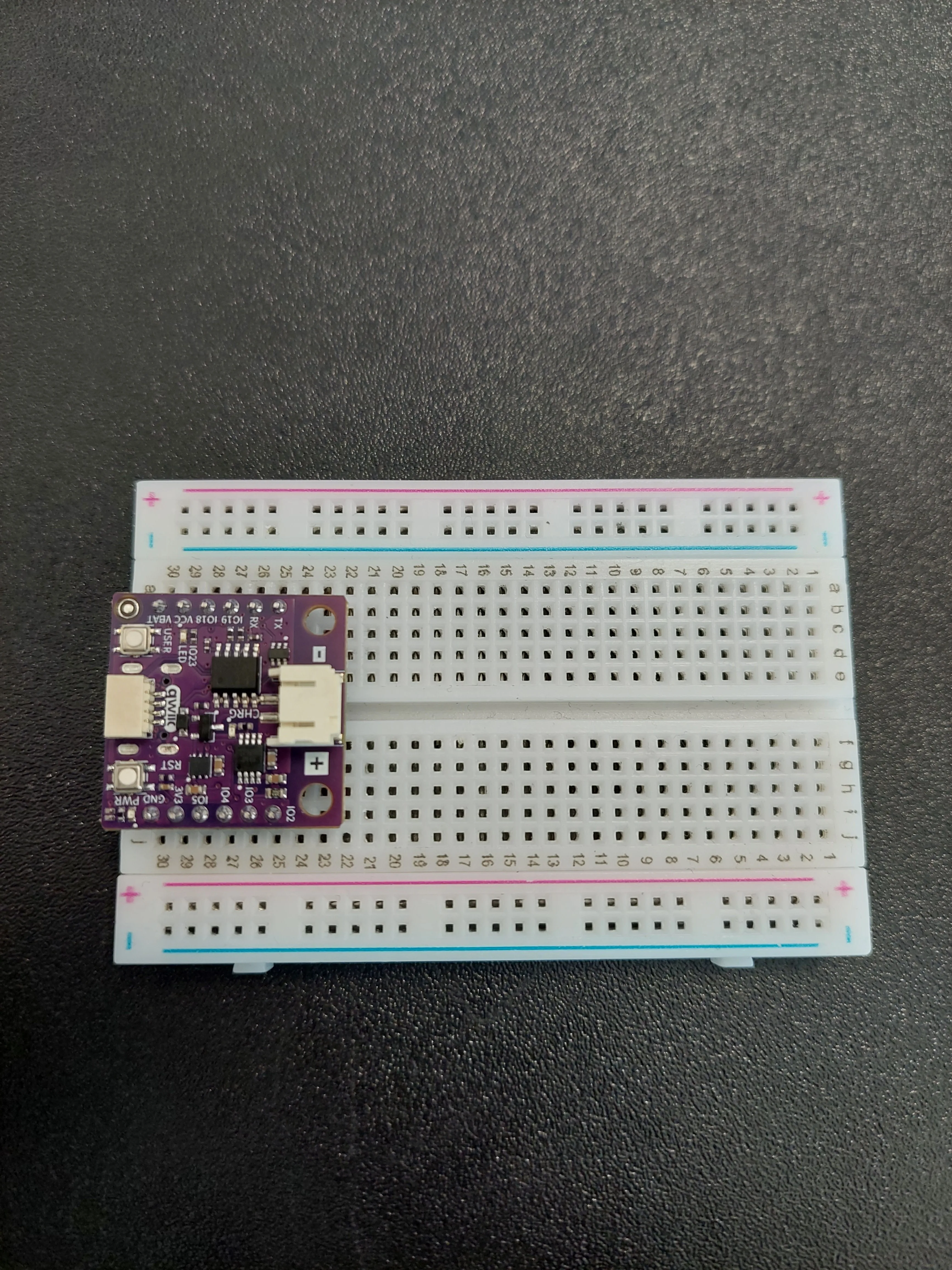
IO4, which is the pin this example needs. On the a–e side the very same row 27 is IO19, a completely different pin. They are not connected to each other. Count your rows on the f–j side, the side where the silkscreen reads IO2 IO3 IO4 IO5 3V3 GND.1. Insert the NULA MINI board on the breadboard
Push the board into one end of the breadboard so that its two rows of pins sit on either side of the centre channel, with the chip facing down. It will occupy rows 25 to 30.
2. Bring IO4 out to a free row
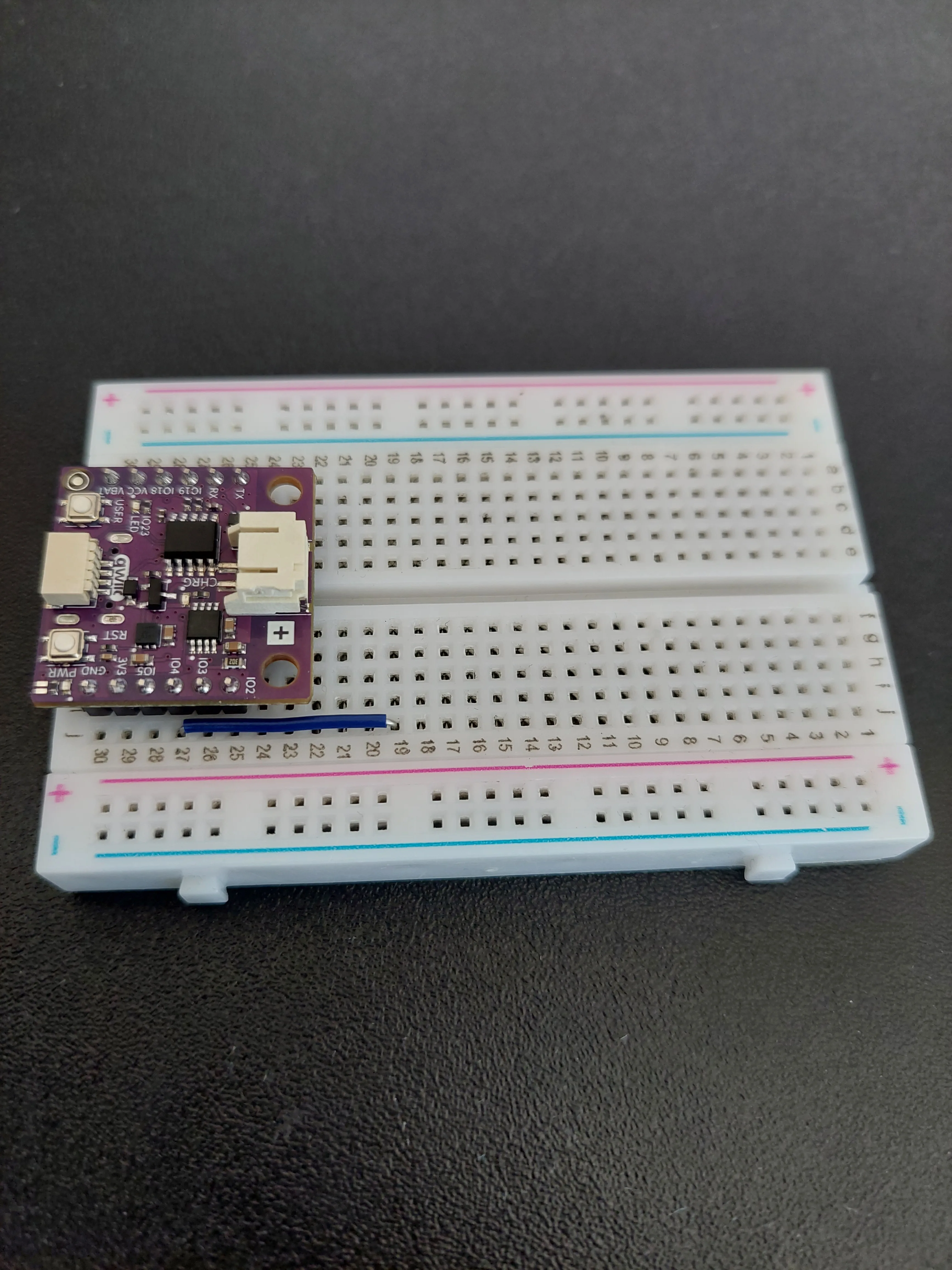
IO4 is the pin that will drive the LED, and the board covers all of row 27 except the outermost hole. So the first wire simply carries that pin somewhere you can work: a jumper from j27 along to j19.
3. Add the 330 Ω resistor
The resistor is the next link in the chain. Place it so it bridges row 19, the row the jumper just arrived in, and row 14, both on the f–j side.
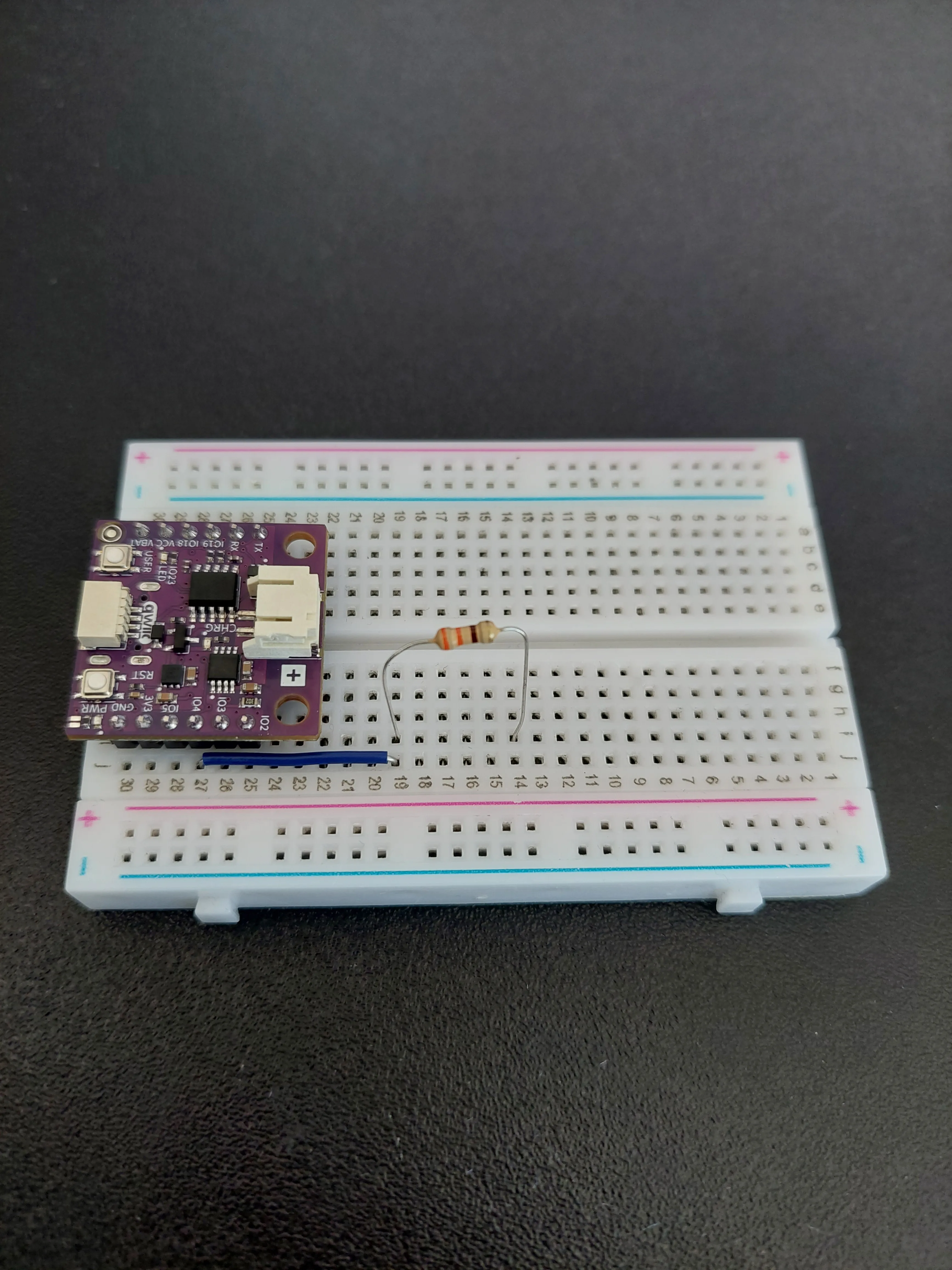
j19 and the resistor in i19, different holes in the same row, so they are already joined. Pick whichever hole your component's legs reach comfortably.4. Add the LED
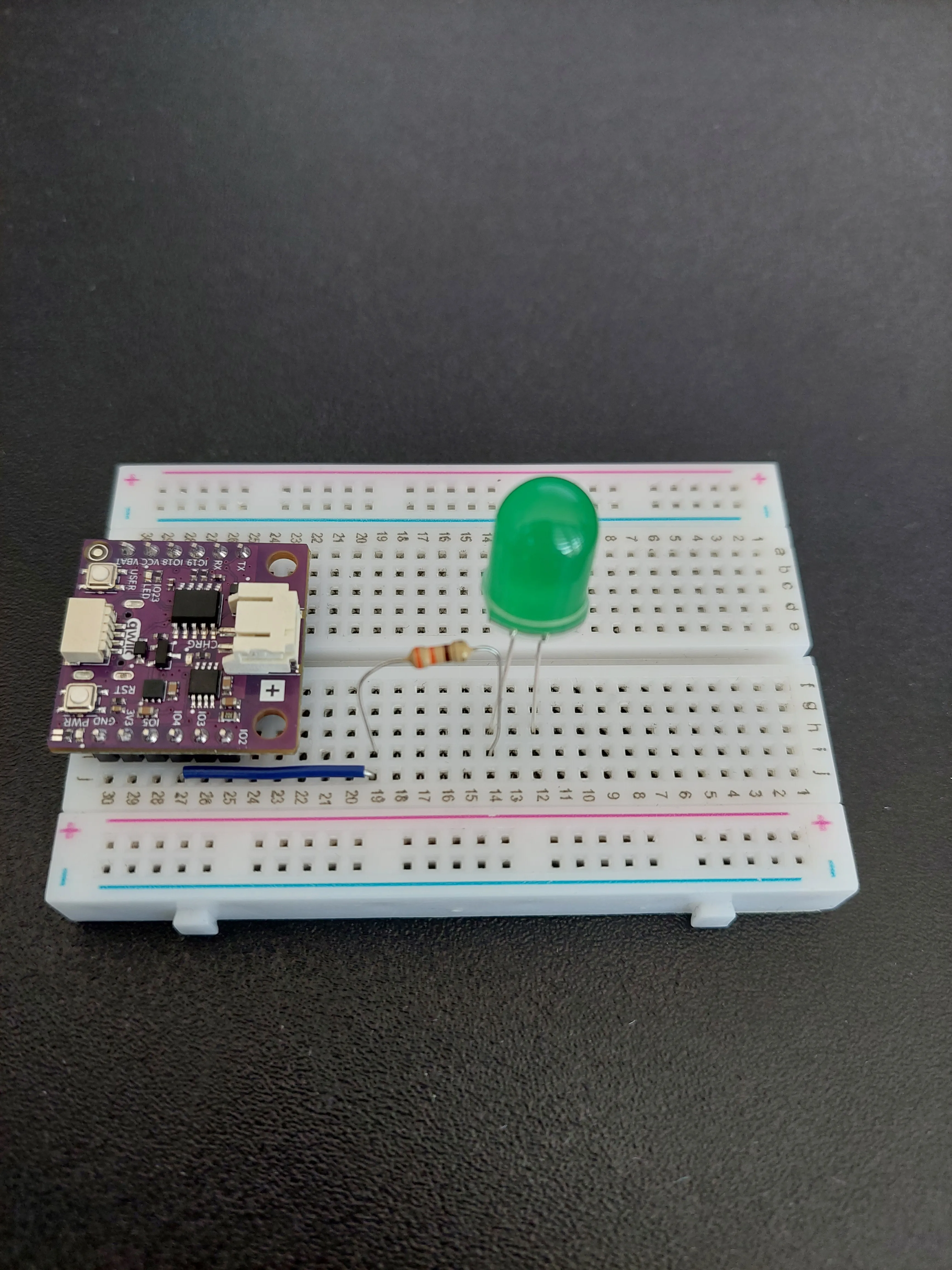
The LED continues the chain: its long leg (anode) into row 14, the same row the resistor ends in, and its short leg (cathode) into row 12.
5. Ground the LED and the board
Two jumpers finish the circuit, and both go to the blue − rail, which acts as a shared ground line:
- From row 12, where the LED's short leg sits, across to the blue − rail.
- From j30 (
GND) across to that same rail.
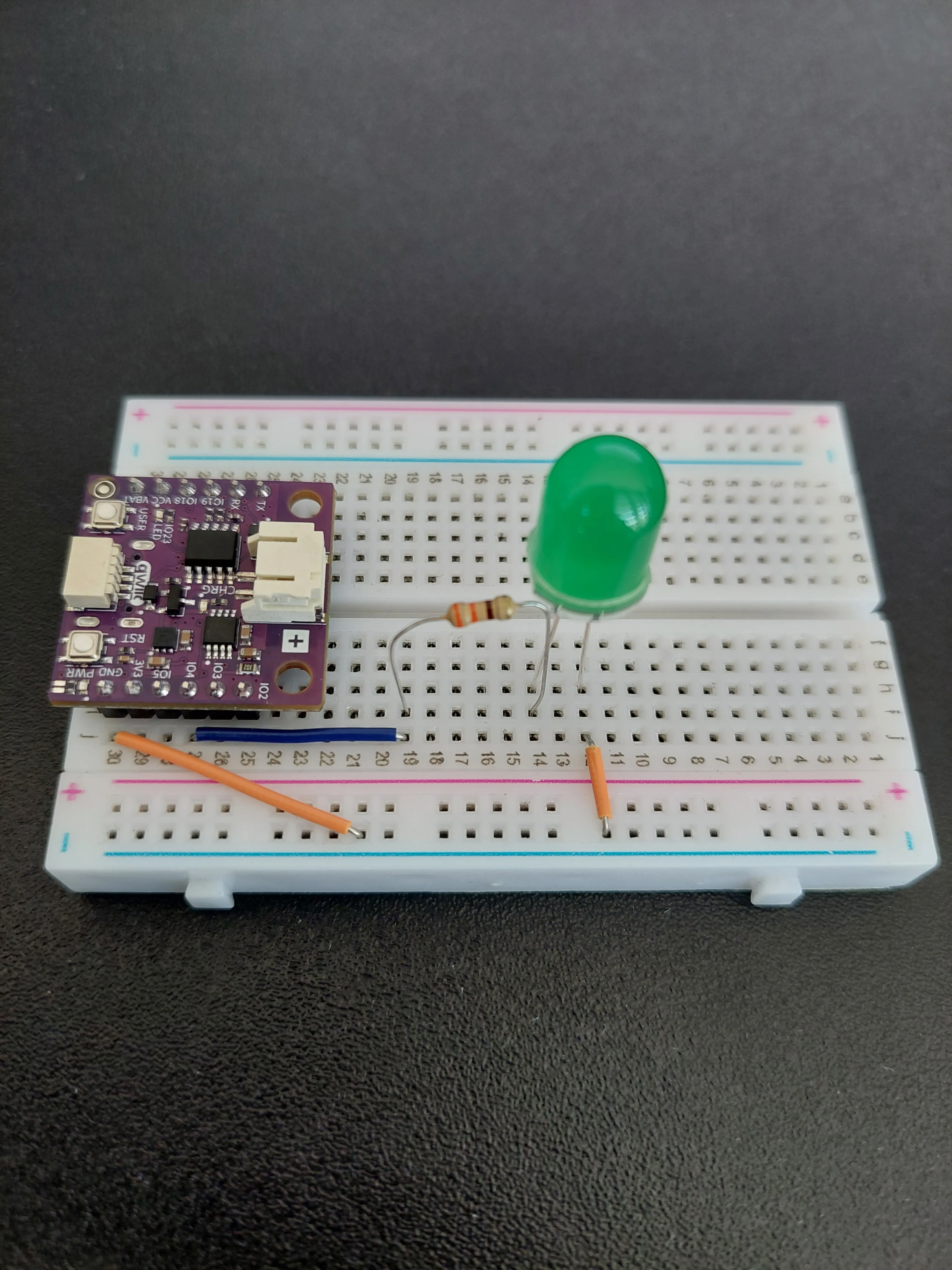
The circuit is now a single unbroken chain: IO4 → row 19 → resistor → row 14 → LED → row 12 → the − rail → GND. Current can only flow when the sketch drives IO4 high, which is exactly what the ON button will do.
6. Connect the board to your computer
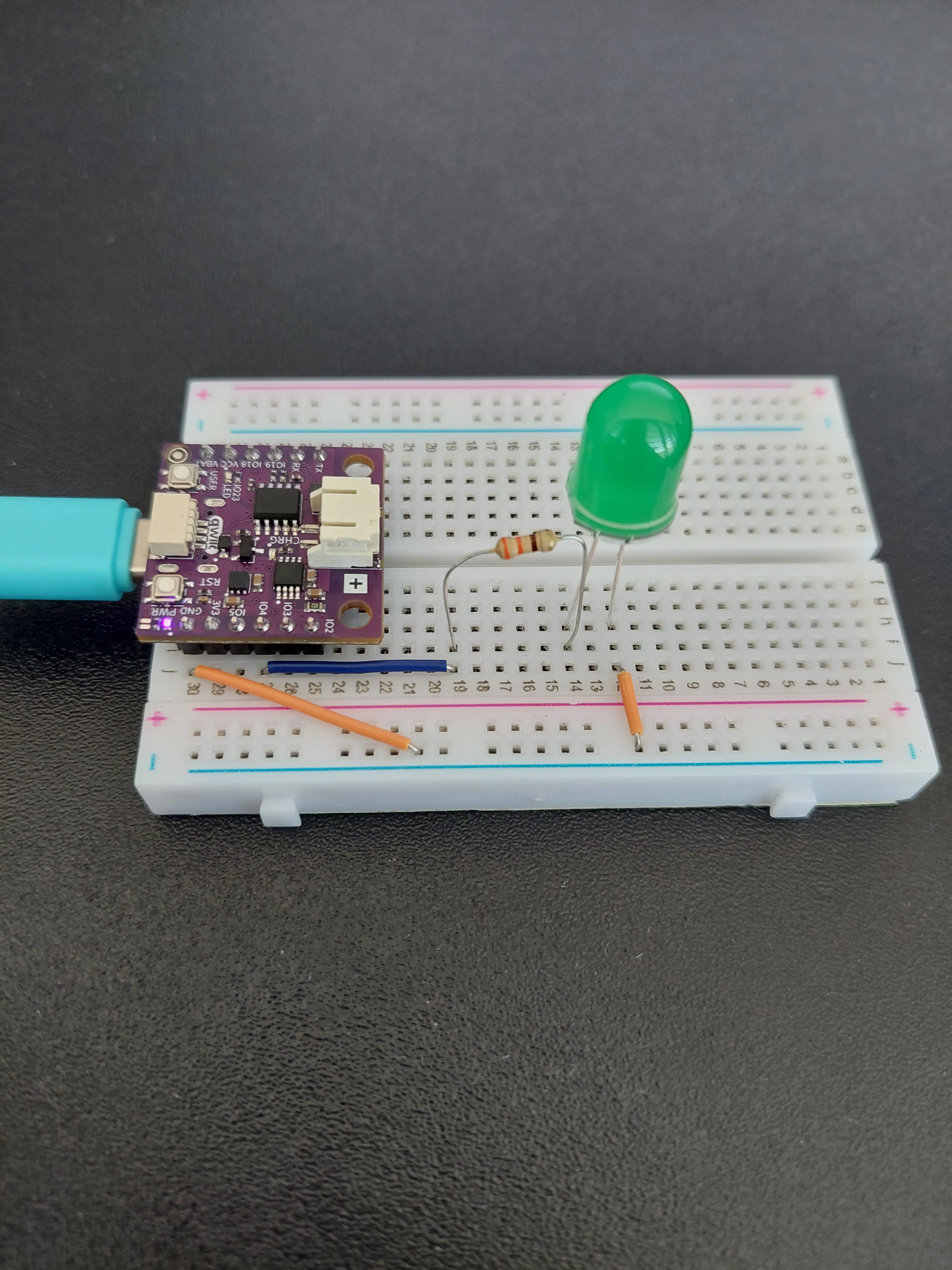
Plug the USB-C cable into the board and into your computer. The PWR LED on the board lights up straight away, but the green LED on the breadboard stays dark. The sketch deliberately switches it off as it starts, so that the page and the hardware agree from the very first moment.
How the board becomes a web server
In 6.1 the board was a client. It picked a website, asked for a page and waited for the answer. Everything started with the board.
Here it is a server, which means it does the opposite: it sits and waits, and something else starts the conversation. When you type the board's address into a browser, the browser sends a request and the board answers. The board never decides when this happens. Your finger on the ON button does.
Ports and routes
A server needs a port, which you can think of as a numbered door on the board. Port 80 is the standard door for web pages, which is why WebServer server(80); lets you simply type an address without adding anything after it. Browsers already try door 80 by default.
Behind that door the board keeps a short list of addresses it knows how to answer. Each entry pairs an address with a function, and those functions are called handlers:
| Address | Handler | What it does |
|---|---|---|
/ | handleRoot() | sends the web page itself |
/led/on | handleLedOn() | drives IO4 high and answers on |
/led/off | handleLedOff() | drives IO4 low and answers off |
/led/status | handleLedStatus() | reads IO4 and reports its current state |
The server.on() lines in setup() are what build that list. This is called routing. Notice that the handler names are passed without brackets: server.on("/led/on", handleLedOn) hands over the function itself, to be called later, rather than calling it there and then.
You never call these four functions anywhere in the sketch. The server calls them for you, each time a request arrives at the matching address.
Why loop() looks so empty
loop() contains a single line, server.handleClient(), and that line is doing all the work. Each time round, it checks whether a browser has sent anything and runs the matching handler if so.
This is why the loop must keep turning freely. Put a long delay() in there and the page becomes sluggish or stops answering altogether, because nothing is checking the door while the board waits.
The page lives inside the sketch
The whole web page is stored in the sketch as one long piece of text, wrapped in R"rawliteral( ... )rawliteral". That wrapping is a C++ convenience: it lets the text run over many lines and contain quotation marks without needing an escape character in front of every one.
PROGMEM then tells the board to keep that text in its flash memory rather than in its much smaller working memory. The page is HTML, the same language the website in 6.1 sent back to us. Now the board is the one sending it.
Inside the page is a short piece of JavaScript, which runs in the browser rather than on the board. It asks /led/status for the current state and writes it into the status line, then repeats that every two seconds:
updateStatus();
setInterval(updateStatus, 2000);
That is why the status line stays honest even if somebody else presses a button on another phone, and also why it can lag: the page can be up to two seconds behind the LED.
nulamini.local instead of an IP address
MDNS.begin("nulamini") claims a name on your local network using mDNS, or Multicast DNS. It lets the board answer to http://nulamini.local/, which is far easier to remember than the address the router handed out.
Like the begin() functions on the sensors in earlier examples, it returns true on success and false on failure, so the sketch checks the result and prints a message either way.
nulamini.local does not open, use the IP address instead. mDNS is not supported everywhere. Windows 10 and 11, macOS and iOS all resolve .local names out of the box, but some Android versions and some routers do not. This is exactly why the sketch prints IP address: to the Serial Monitor. Type those numbers into your browser and you reach the same page. The name is a convenience, not a requirement.Setting up Wi-Fi credentials
Before uploading, change these two lines to match your own network:
const char* ssid = "your ssid";
const char* password = "your password";
Code
Below is the complete code for this example:
/**
 **************************************************
 *
 * @file        6.2_Wi-Fi_LED_Control.ino
 * @brief       Example that shows how to control an LED from a web page. The NULA board joins your Wi-Fi network and
 *              then becomes a small web server of its own, which means you can open it in the browser of your phone
 *              or computer. The page has an ON and an OFF button and shows the current state of the LED.
 *              In the previous example the board asked a website for data, here the board is the one being asked.
 *              For details, connection diagram and more, check out the example documentation at: <link placeholder>
 * @author      Soldered
 ***************************************************
 */

/*
The WiFi library contains everything needed to join a Wi-Fi network.
*/
#include <WiFi.h>

/*
The WebServer library does the hard work of being a web server: it listens for browsers that want to connect and
hands each request over to a function we wrote.
*/
#include <WebServer.h>

/*
The ESPmDNS library lets the board announce itself on your network under a friendly name. Thanks to it you can open
http://nulamini.local/ in your browser instead of having to remember the IP address.
*/
#include <ESPmDNS.h>

/*
These two variables hold the name of your Wi-Fi network (the SSID) and its password. Replace the text between the
quotation marks with your own network details. Your phone or computer has to be on the same network as the board,
otherwise it will not be able to reach the page.
*/
const char* ssid = "your ssid";
const char* password = "your password";

/*
This is a variable to which we pass the number of pin that we had connected the LED to.
The NULA board has a pin naming logic as follows: IO4, where 4 is the number that we give to the variable.
If you wish to use a different pin, make sure you are using a IO__ marked pin.

Remember that the LED needs a 330 Ohm resistor in series with it. That resistor limits how much current flows, and
without it the LED draws more than either it or the pin is built for, so both can be damaged.
*/
const int LED_PIN = 4;

/*
Here we create our web server object, which we named "server". The number 80 is the port it listens on. A port is
like a door number on the board: port 80 is the standard door for web pages, which is why browsers try it by default
and why we do not have to type it into the address bar.
*/
WebServer server(80);

/*
This is the web page itself, written in HTML and stored as one long piece of text. HTML is the language that
describes what a page looks like, the same language example.com sent us in the previous example.
The R"rawliteral( ... )rawliteral" wrapping is a C++ trick that lets us write many lines of text, including
quotation marks, without having to escape every one of them.
PROGMEM tells the board to keep this text in its flash memory rather than in its much smaller working memory.
The page contains two buttons and a small piece of JavaScript, which is code that runs inside the browser and asks
the board for the current LED state every two seconds so the displayed status stays up to date on its own.
*/
const char htmlPage[] PROGMEM = R"rawliteral(
<!DOCTYPE html>
<html>
<head>
  <meta name="viewport" content="width=device-width, initial-scale=1">
  <title>NULA MINI LED Control</title>
  <style>
    body { font-family: Arial; text-align: center; margin-top: 50px; }
    button { padding: 15px 30px; margin: 10px; font-size: 20px; }
    .status { font-size: 24px; margin-top: 20px; }
  </style>
</head>
<body>
  <h1>NULA MINI LED Control</h1>
  <button onclick="fetch('/led/on').then(()=>updateStatus())">ON</button>
  <button onclick="fetch('/led/off').then(()=>updateStatus())">OFF</button>
  <div class="status" id="status">Loading status...</div>

  <script>
    // Function that requests LED status from the NULA MINI and updates the page
    async function updateStatus() {
      let res = await fetch('/led/status');
      let text = await res.text();
      document.getElementById('status').innerHTML = 'LED is ' + text.toUpperCase();
    }

    // Run immediately after page load and update every 2 seconds
    updateStatus();
    setInterval(updateStatus, 2000);
  </script>
</body>
</html>
)rawliteral";

/*
The four functions below are called handlers. A handler is a function that the server runs when a browser asks for
one particular address. We only write them here, we do not call them ourselves anywhere in the program: further down
in setup() we tell the server which address belongs to which handler, and from then on the server calls them for us.

This first handler answers the root address "/", which is what the browser asks for when you simply open the board's
address. It sends back the web page we prepared above.
The three numbers and words in server.send() are the response code (200 means "here you go"), the type of content we
are sending, and the content itself.
*/
void handleRoot() {
  server.send(200, "text/html", htmlPage);
}

/*
This handler answers the address "/led/on". It turns the LED on and answers with the short text "on", which the
JavaScript in the page uses to update the status line.
*/
void handleLedOn() {
  digitalWrite(LED_PIN, HIGH);
  server.send(200, "text/plain", "on");
}

/*
This handler answers the address "/led/off" and does the opposite: it turns the LED off and answers with "off".
*/
void handleLedOff() {
  digitalWrite(LED_PIN, LOW);
  server.send(200, "text/plain", "off");
}

/*
This handler answers the address "/led/status" and reports the current state of the LED. digitalRead() gives us the
value the pin currently has, and the question mark is a short way of writing an if statement: if the value is HIGH we
answer "on", otherwise we answer "off".
*/
void handleLedStatus() {
  String status = digitalRead(LED_PIN) ? "on" : "off";
  server.send(200, "text/plain", status);
}

void setup() {

  /*
  Serial.begin() establishes serial communication between your board and your computer via a USB cable. We use it here
  to follow the connection process and to find out the address of the board.
  */
  Serial.begin(115200);

  /*
  pinMode() is a function that configures the specified pin to behave either as an input or in this case as an output.
  As our pin needs to turn on the LED, we will put the pin in OUTPUT mode. Right after that we write LOW to it, so
  that the LED starts out switched off and the status shown on the page matches reality.
  */
  pinMode(LED_PIN, OUTPUT);
  digitalWrite(LED_PIN, LOW);

  /*
  WiFi.begin() starts the connection attempt. The function only starts the process, it does not wait for it to finish.
  */
  Serial.println("Connecting to WiFi...");
  WiFi.begin(ssid, password);

  /*
  Because of that, we wait for the connection ourselves. WiFi.status() tells us the current state and WL_CONNECTED is
  the value it reports once we are online. The dots (".") show progress in the Serial Monitor.
  */
  while (WiFi.status() != WL_CONNECTED) {
    delay(500);
    Serial.print(".");
  }

  /*
  WiFi.localIP() returns the address the router handed out to our board. Typing this address into a browser on the
  same network opens the page we prepared above.
  */
  Serial.println("\nWiFi connected!");
  Serial.print("IP address: ");
  Serial.println(WiFi.localIP());

  /*
  MDNS.begin() claims a name on the local network, in this case "nulamini". If it succeeds, the board can also be
  reached at http://nulamini.local/, which is far easier to remember than a row of numbers. Like begin() functions on
  sensors, it returns true on success and false on failure, so we check the result and print a message either way.
  */
  if(MDNS.begin("nulamini")){
    Serial.println("mDNS responder started!");
    Serial.println("Access the board in your browser at: http://nulamini.local/");
  } else {
    Serial.println("Error starting mDNS responder!");
  }

  /*
  server.on() connects an address to one of the handler functions we wrote above. This is called routing. From here on
  the server knows that a browser asking for "/led/on" should be answered by handleLedOn(), and so on for the rest.
  Notice that we pass the name of the function without brackets: we are handing over the function itself, not calling
  it right now.
  */
  server.on("/", handleRoot);
  server.on("/led/on", handleLedOn);
  server.on("/led/off", handleLedOff);
  server.on("/led/status", handleLedStatus);

  /*
  server.begin() opens the door and starts listening for browsers.
  */
  server.begin();
  Serial.println("HTTP server started");
}

void loop() {

  /*
  server.handleClient() checks whether a browser has sent us anything and, if it has, runs the matching handler
  function. This is the reason the loop has to keep running: if we stopped calling this function the page would stop
  responding. For the same reason, avoid long delay() calls in this loop.
  */
  server.handleClient();
}
What you should see
Open the Serial Monitor at 115200 baud right after uploading. The board reports its whole start-up sequence:

Reading that from the top:
- The first nine lines (
ESP-ROM,Build,rst:0x1and theload:lines) are not from the sketch. They come from the chip's own ROM bootloader as it wakes up and loads your program. Every example prints them; they are normal, and they appear beforesetup()has run a single line. Connecting to WiFi...is the sketch's first message. The three dots at the end of it are just punctuation, part of the text.- The dots on the next line are the real progress indicator. Each one is a single pass of the wait loop, and each pass takes 500 ms, so the row of dots is a stopwatch. Fourteen dots here means about seven seconds to join the network.
IP address: 192.168.75.75is the address the router handed out. Yours will differ. Keep it. It is your fallback ifnulamini.localwill not open.mDNS responder started!confirms the friendly name was claimed, and the line after it gives you the address to type.HTTP server startedis the last line. From here the board is listening andloop()is running.
WiFi.status() never reaches WL_CONNECTED, so the board prints dots forever and never gets as far as reporting an error. A dot row that keeps growing past twenty or thirty is not a slow network. It is almost always a typo in the credentials.Opening the page
With the board reporting HTTP server started, open http://nulamini.local/ on any phone or computer on the same network. The page is deliberately plain:

The status line is not a guess. Before the page has finished loading, the JavaScript has already asked /led/status, and the board has read IO4 and answered. LED is OFF is a real measurement of a real pin, and the breadboard agrees:
Now press ON:

And the LED on the breadboard lights up:
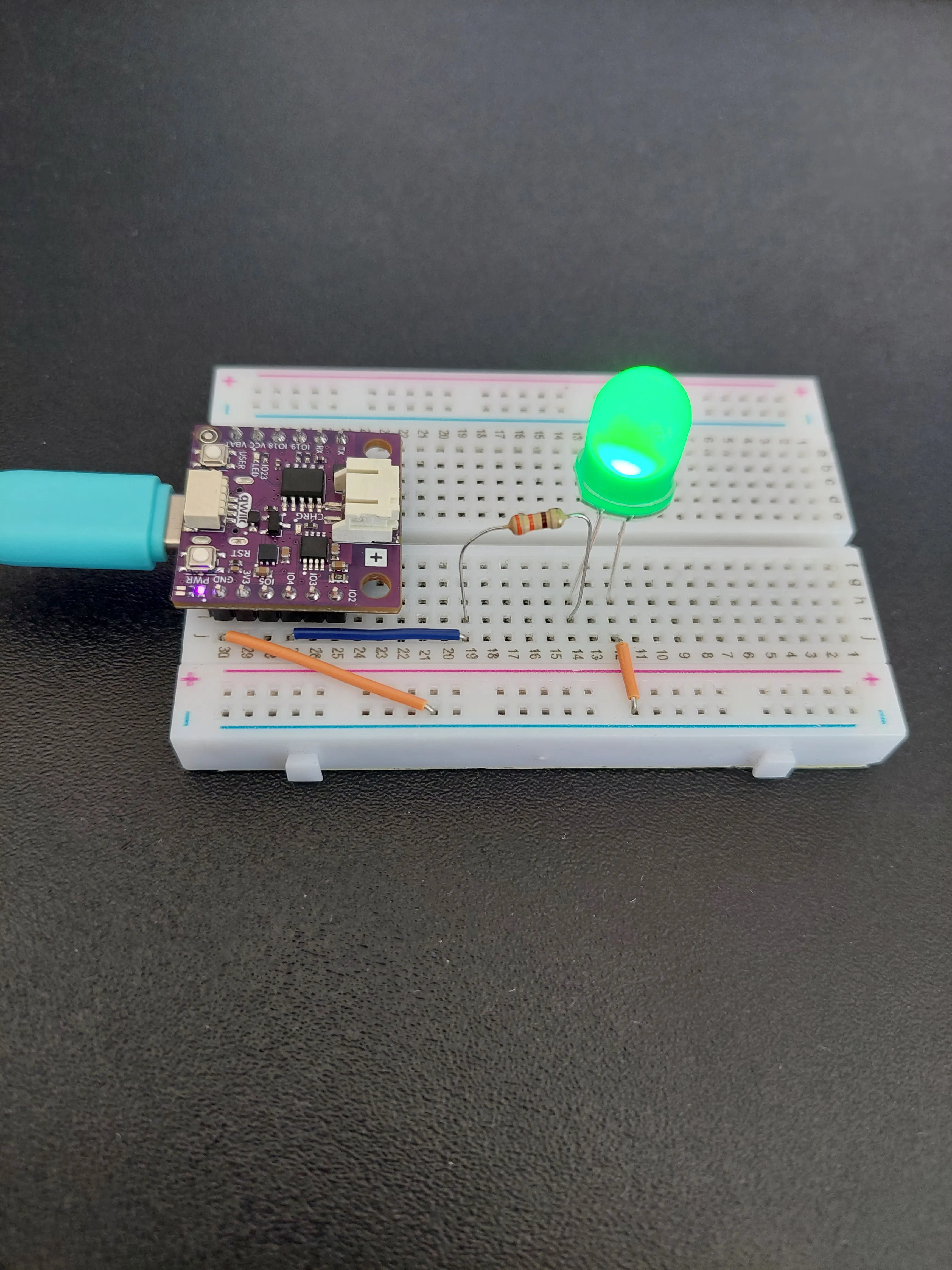
Nothing about the wiring moved between those two photos. The only difference is the voltage on IO4, and that came from a button press somewhere else on your network.
The press travels a long way for something that looks so simple. Your finger triggers a fetch('/led/on') in the browser, which sends an HTTP request across your router to the board. server.handleClient() picks it up, matches the address to handleLedOn(), and that function calls digitalWrite(LED_PIN, HIGH). Current then flows from IO4 through the resistor, through the LED and into the − rail. Pressing OFF does the same journey in reverse.
Full example
Check out the full example code on the link below:
6.2_Wi-Fi_LED_Control.ino
Example that shows how to control an LED on the NULA MINI from a web page, served by the board itself and reachable at nulamini.local.