7.2 Mini Piano
This project turns four buttons and a passive buzzer into a small piano. Each button gets a note of its own, and holding it down plays that note for as long as you keep your finger there.
Nothing here is new. The buttons are read exactly as in 2.1 Button Counter, and the buzzer is driven exactly as in 2.4 Buzzer Beep. What makes it a project is the scale: four inputs and one output on the breadboard at once, and the first build in this kit that uses pins on both sides of the board.
In this documentation you will learn:
- How to wire four buttons at once, each to its own pin
- How to join the two blue − rails into a single shared ground
- How
tone()turns a number into a pitch, andnoTone()stops it - Why an
else ifchain means only one note can sound at a time
Hardware required:
- 1x Soldered NULA MINI board
- 1x Breadboard
- 4x Push buttons
- 1x Passive buzzer
- 12x Jumper wires
- 1x USB-C cable
INPUT_PULLUP. And not for the buzzer: the pin only ever swings between 0 V and 3.3 V, so there is nothing to protect it from. If you have seen a piano circuit drawn with four 10 kΩ resistors, that is a different way of wiring buttons and it is not what this sketch expects.Putting the components together
This build uses five pins on the board, and they are split across both sides of it:
| Pin | Row | Side | What it does |
|---|---|---|---|
IO2 | 25 | f–j | Button 1, note C4 |
IO3 | 26 | f–j | Button 2, note D4 |
IO4 | 27 | f–j | Button 3, note E4 |
IO5 | 28 | f–j | Button 4, note F4 |
IO18 | 28 | a–e | Buzzer |
GND | 30 | f–j | Ground for everything |
IO5, one of the buttons. On the a–e side row 28 is IO18, the buzzer. They sit at opposite ends of the same row number and are not connected to each other. Read the name printed on the board, never the row number on its own.The board body covers the middle columns, so beside it only column a on the a–e side and column j on the f–j side are free. Every wire that touches the board therefore goes into an a… or a j… hole.
Follow the eight steps below. Each photo is taken from the same position, so you can compare it with the previous one and see exactly what changed.
1. Insert the NULA MINI board on the breadboard
Push the board into one end of the breadboard so that its two rows of pins sit on either side of the centre channel, with the chip facing down. Press it in evenly until all the pins are seated.
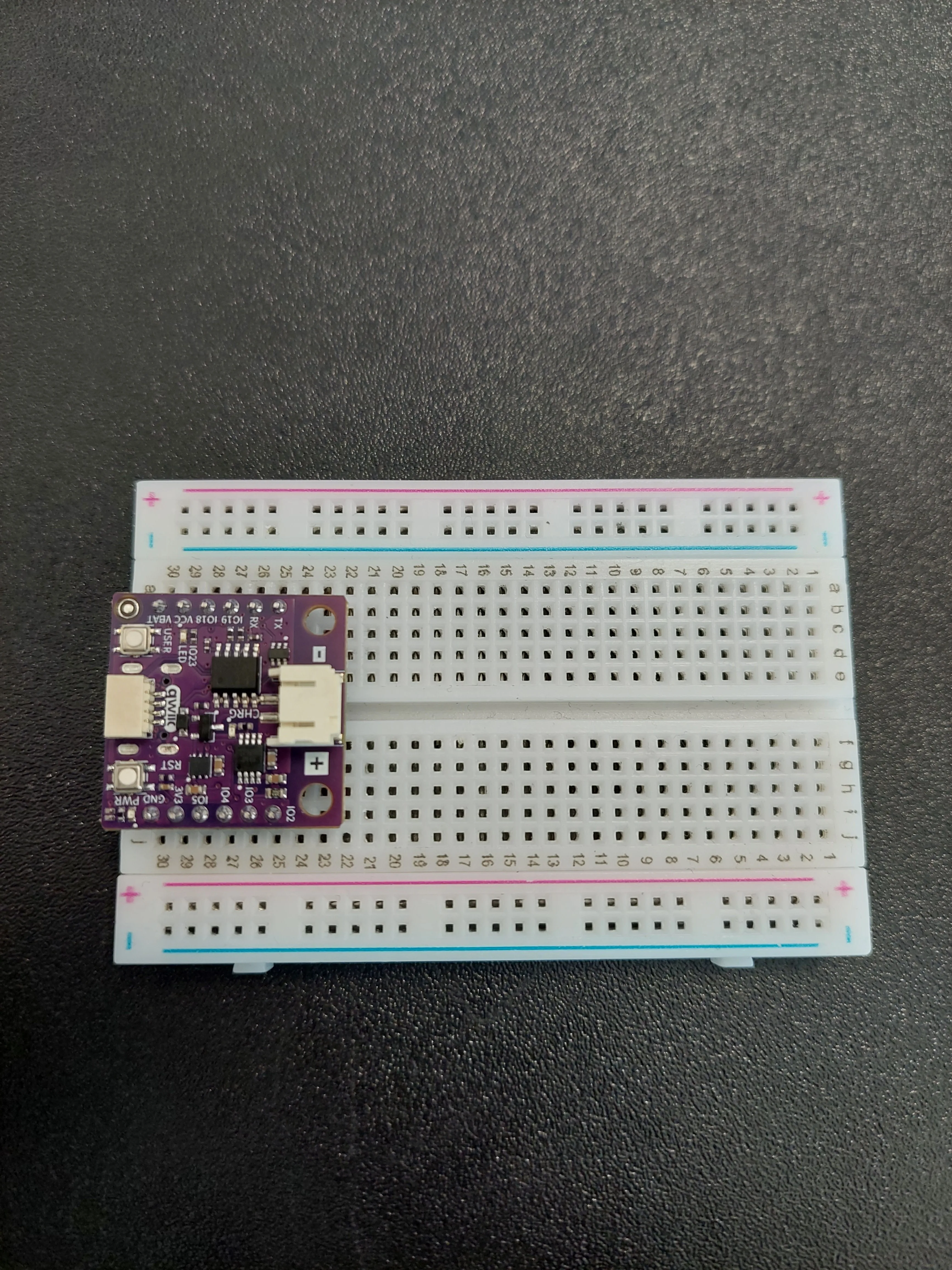
In the photos that follow, the board occupies rows 25 to 30.
2. Bring ground out to the blue − rail
One short jumper from j30 (the row holding GND) across to the blue − rail on the f–j edge.
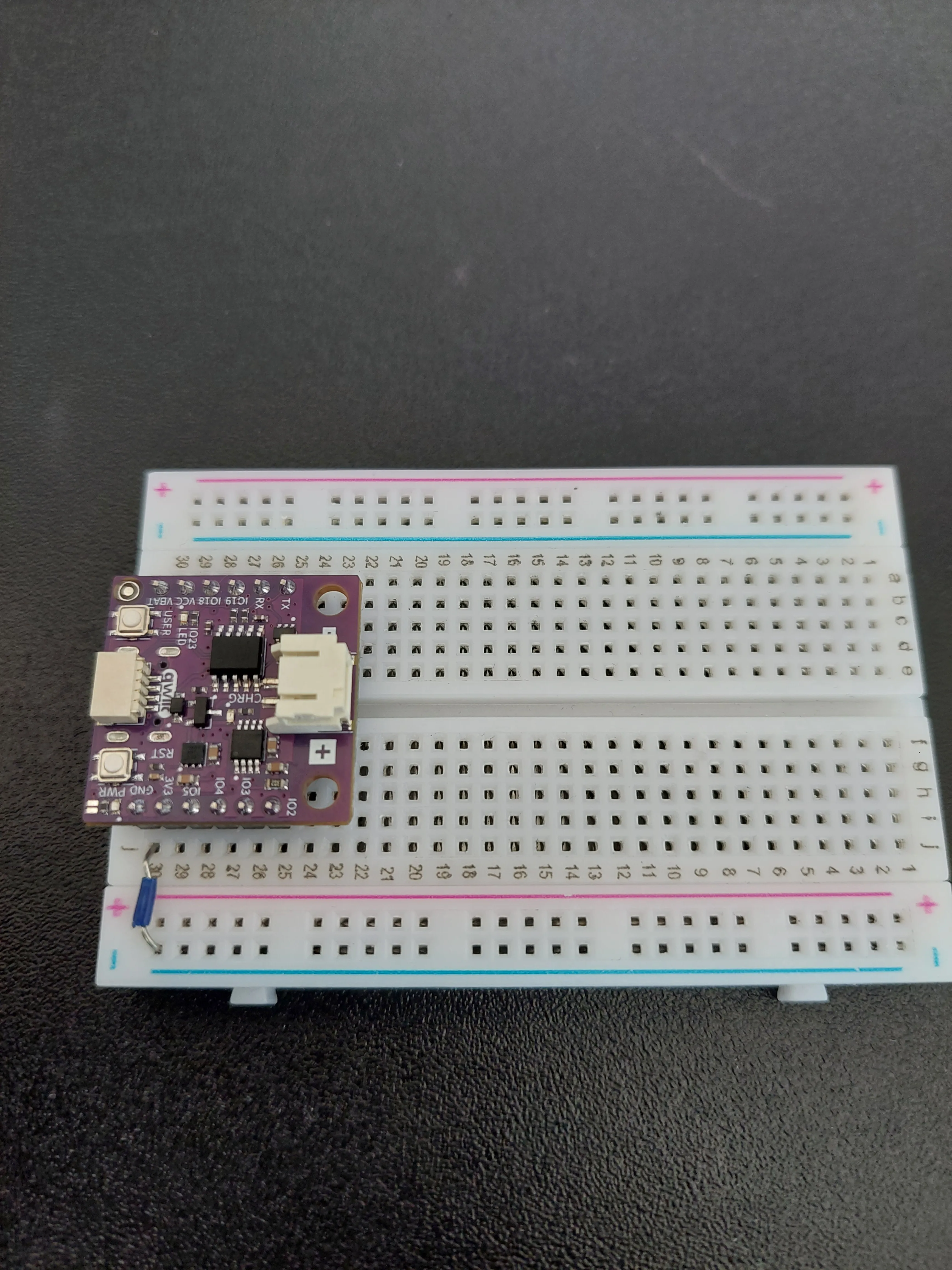
3. Join the two blue − rails together
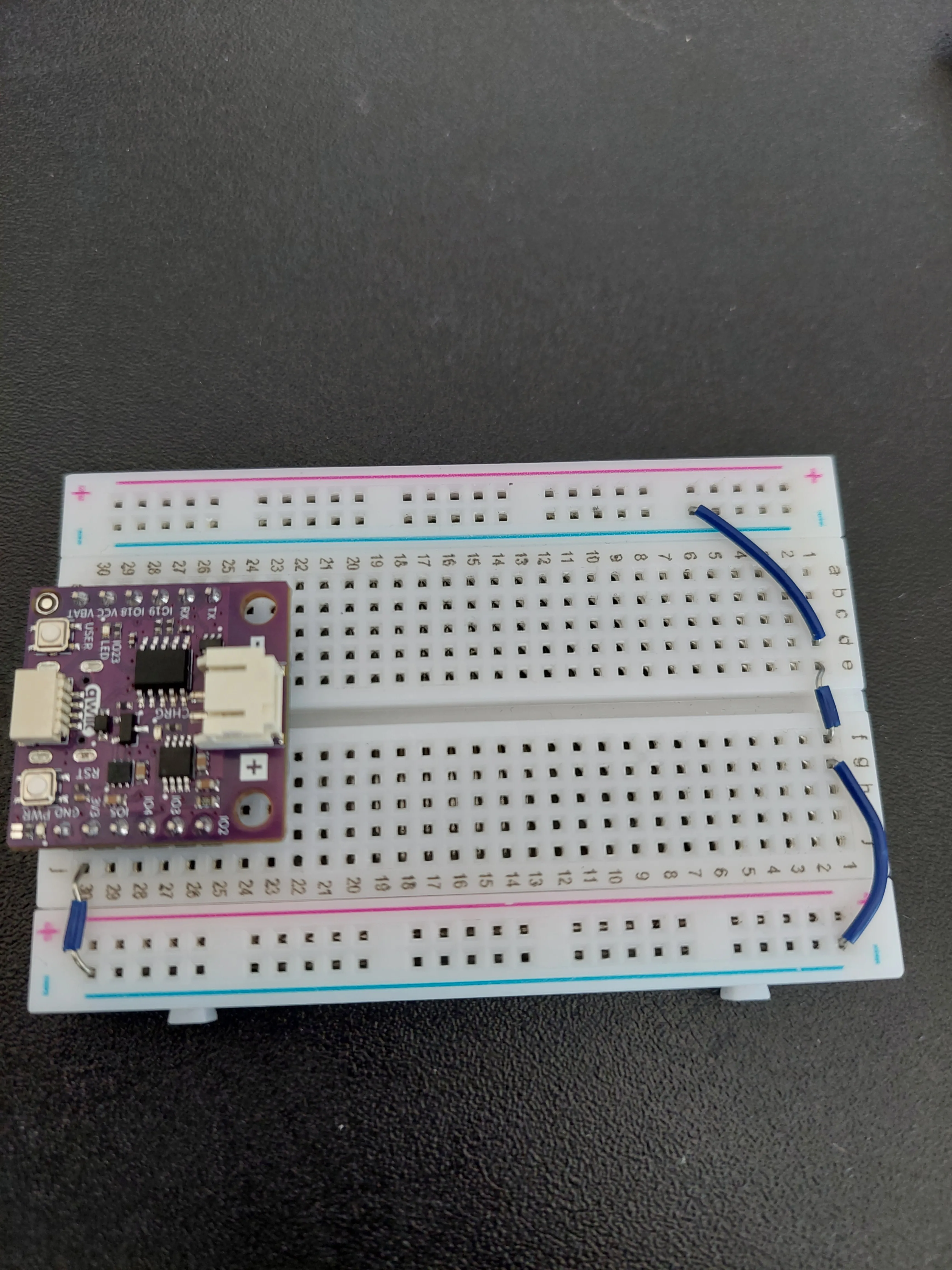
The buttons and the buzzer will take their ground from the a–e edge, but GND came out on the f–j edge. So the two blue − rails have to be joined into one.
Run a jumper from the blue − rail on the f–j edge, around the far end of the breadboard, to the blue − rail on the a–e edge. Put it down near row 1, well clear of everything else.
4. Place the four push buttons
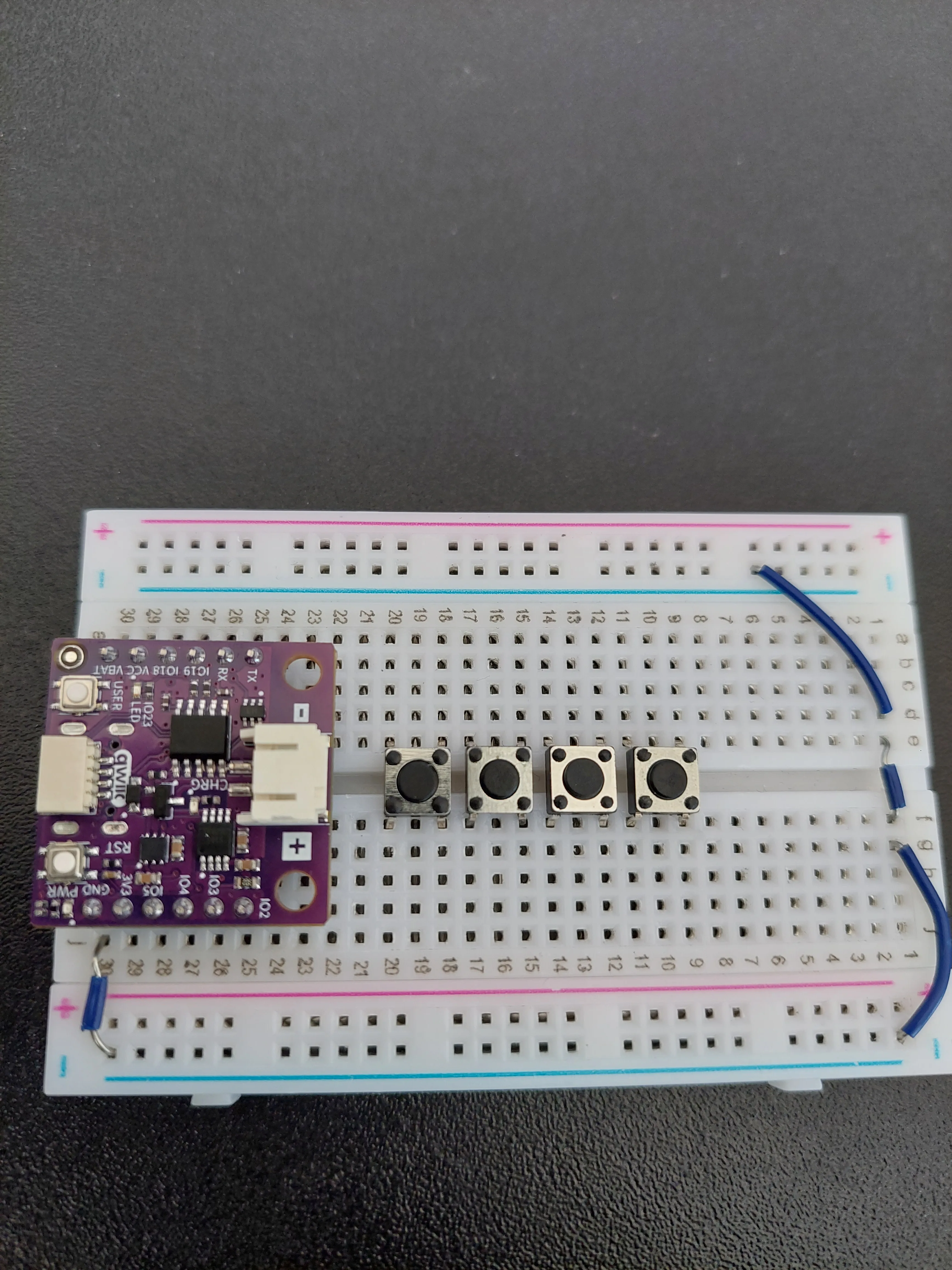
Push the four buttons into the middle of the breadboard so that each one straddles the centre channel, a few rows clear of the board. Each button spans two rows.
In the photos they sit in rows 18 and 20, 15 and 17, 12 and 14, and 9 and 11, nearest the board first, three rows apart, which is comfortable spacing for four fingers.
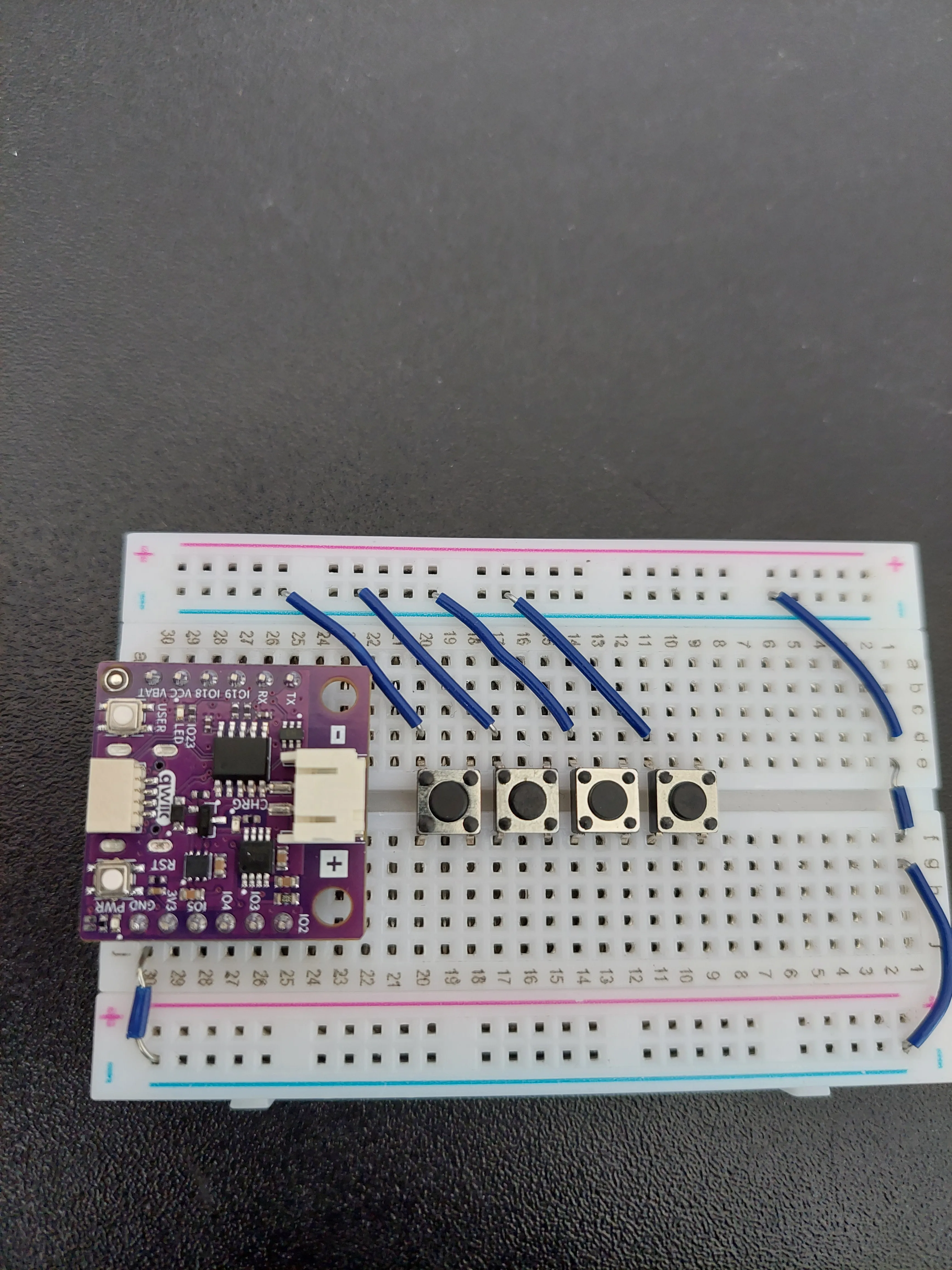
5. Ground each button
Four short jumpers, one per button, from the button's a–e side out to the blue − rail on that edge. In the photo those are rows 20, 17, 14 and 11, the higher row of each button's pair.
6. Connect each button to its own pin
Now the four signal wires, all on the f–j side. Each runs from a board pin to the lower row of one button's pair:
| From | To | Button | Note |
|---|---|---|---|
j25 (IO2) | j18 | 1 | C4, 262 Hz |
j26 (IO3) | j15 | 2 | D4, 294 Hz |
j27 (IO4) | j12 | 3 | E4, 330 Hz |
j28 (IO5) | j9 | 4 | F4, 349 Hz |
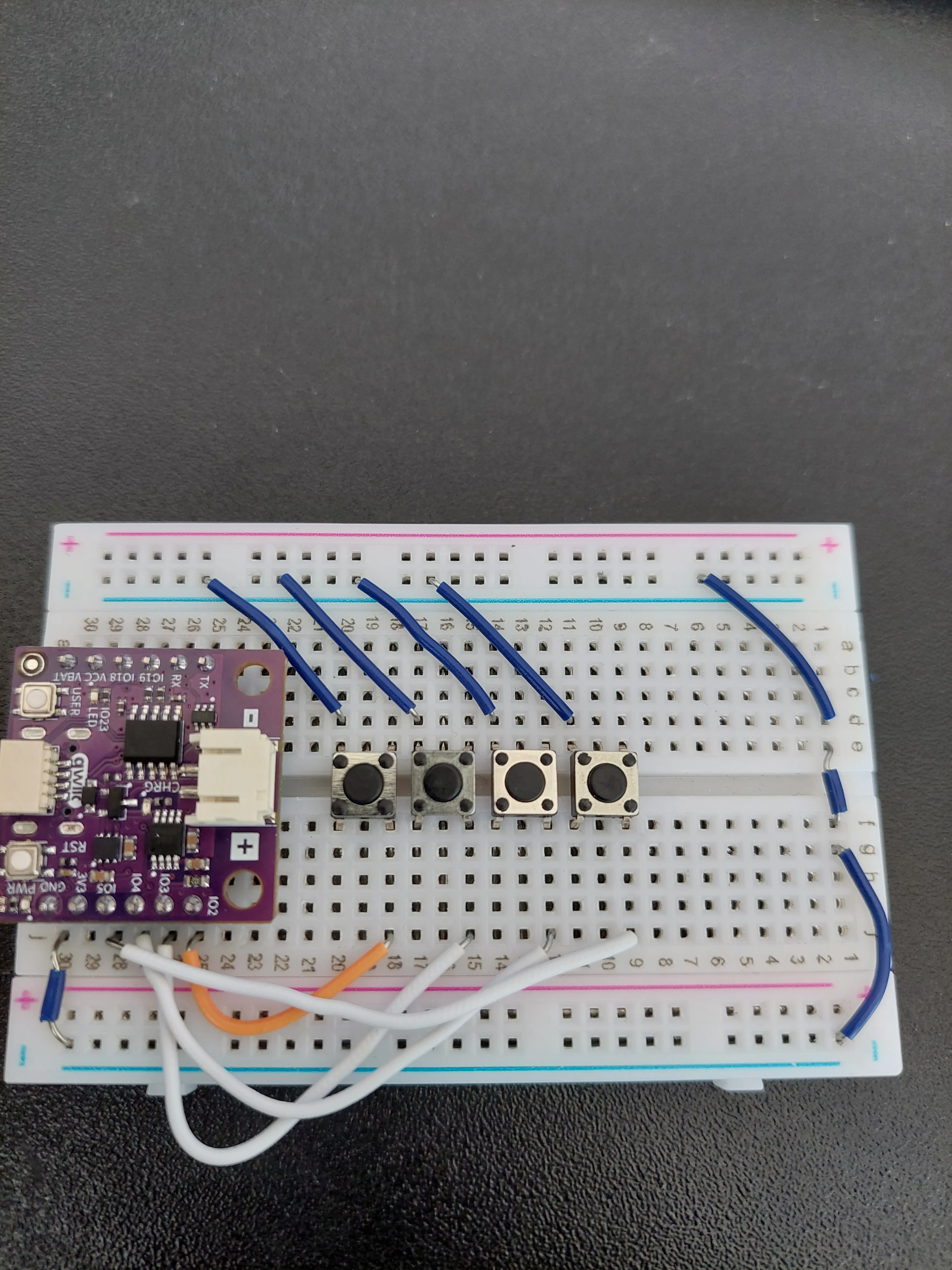
Notice that the four wires run in parallel and never cross. IO2, the pin nearest the buttons, goes to the nearest button; IO5, the furthest pin, goes to the furthest button. Keeping that order is what makes the notes climb as your hand moves away from the board, and it is worth double-checking, because all four wires look alike once they are in.
7. Place the buzzer and wire it up
The buzzer goes on the a–e side, at the far end of the breadboard, with its legs in two neighbouring rows, rows 3 and 4 in the photo.
Look at the top of its case before you push it in. Next to the HWDZ moulding there is a small + inside a circle, and the leg on that side of the case is the positive one. That leg goes into row 4.
Then two wires:
- From a4, the row holding the + leg, to a28, which is
IO18. This is the wire that carries the square wave. - From a3, the buzzer's other leg, to the blue − rail on the same edge.
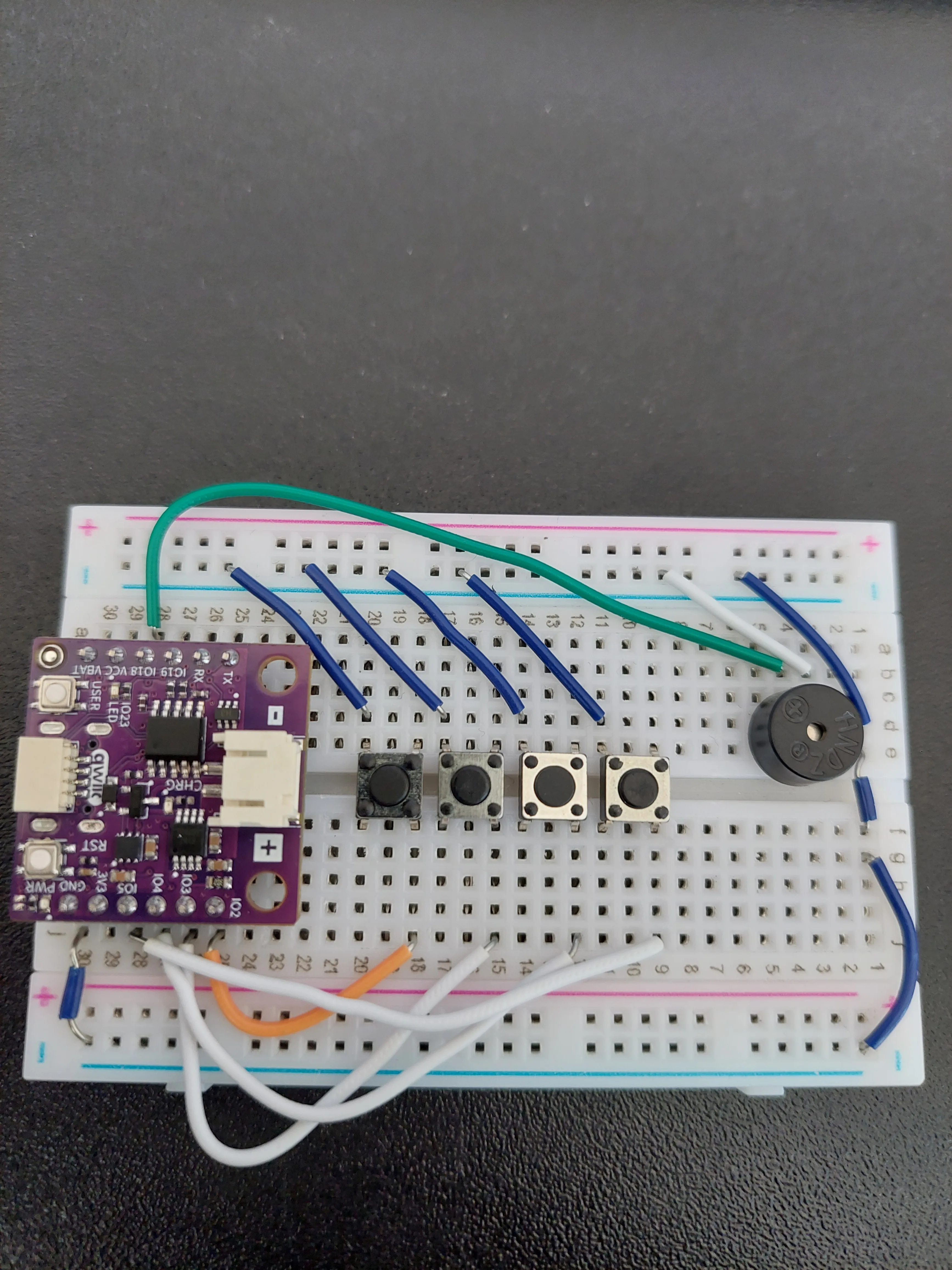
The loop is now closed: IO18 → buzzer → GND. The 12 mm case hides the legs once the buzzer is pushed in, so if you need to check the wiring later, read the two jumpers instead.
8. Connect the board to your computer
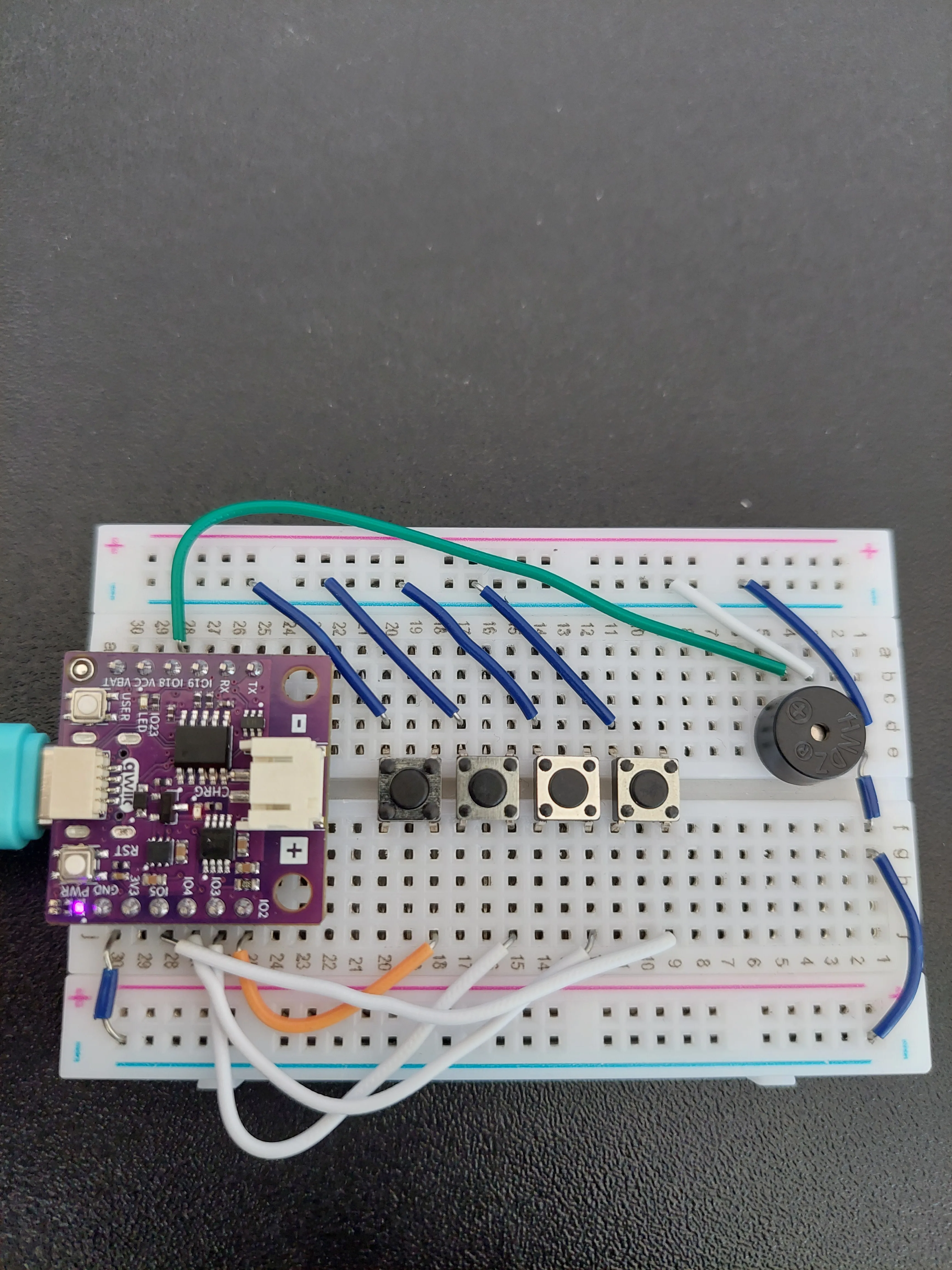
Plug the USB-C cable into the board. The PWR LED lights up as soon as it has power.
IO18 on the + one.How four buttons share one buzzer
Reading a button. Each of the four pins is set up with INPUT_PULLUP, which switches on a resistor inside the chip that gently ties the pin to 3.3 V. The pin therefore reads HIGH while its button is released, and the button's only job is to connect that pin to GND, which drags it down to LOW.
Making a note. tone() switches IO18 between 3.3 V and 0 V over and over. That is a square wave. The number of switches per second is the frequency, and your ear reads frequency as pitch. Four frequencies, four notes:
| Note | Frequency (Hz) |
|---|---|
| C4 | 262 |
| D4 | 294 |
| E4 | 330 |
| F4 | 349 |
These are the first four notes of the C major scale, starting from the C in the middle of a piano keyboard. Change the numbers and you change the tuning. There is nothing special about these four values, and looking up the frequency of any other note is enough to build your own scale.
Only one note at a time. The four checks in loop() are joined into a single if / else if chain, so the board stops at the first button it finds pressed and never looks at the rest. Press two keys together and you hear only the one that comes earlier in the chain, which is the lower note. A real piano plays chords; this one cannot, and the else if chain is the reason.
Letting go. When none of the four is pressed the chain falls through to its else and calls noTone(), which stops the sound. That is what makes a note last exactly as long as you hold the key down.
delay(50) at the end of loop() gives the button contacts a moment to settle so that one press is not read as several, the same debouncing idea as 2.2 Button Debounce. It also means the board looks at the buttons 20 times a second, so up to 50 ms can pass between your finger landing and the note starting. You can just about feel it if you play quickly.Code
/**
 **************************************************
 *
 * @file        7.2_Mini_piano.ino
 * @brief       Project that turns four buttons and a passive buzzer into a small piano. Each button has its own
 *              frequency, and pressing it plays that note for as long as you hold the button down.
 *              It builds on the button reading from section 2.1 and the buzzer from section 2.4.
 *              For details, connection diagram and more, check out the example documentation at: <link placeholder>
 * @author      Soldered
 ***************************************************
 */

/*
This is a variable to which we pass the number of pin that we had connected the buzzer to.
The NULA board has a pin naming logic as follows: IO18, where 18 is the number that we give to the variable.
*/
const int BUZZER_PIN = 18;

/*
These are the variables to which we pass the numbers of pins that we had connected the four BUTTONS to. Each button
gets a pin of its own, because the board has to be able to tell them apart.
*/
const int BTN1 = 2;
const int BTN2 = 3;
const int BTN3 = 4;
const int BTN4 = 5;

/*
These are the frequencies of the four notes, in Hertz. A frequency is how many times per second the buzzer moves back
and forth, and it is what our ears hear as the pitch of a sound: the higher the number, the higher the note.
The names come from the musical scale, where C4 is the C in the middle of a piano keyboard. Feel free to experiment
with these values, or look up the frequencies of other notes and build your own scale.
*/
const int NOTE_C4 = 262;
const int NOTE_D4 = 294;
const int NOTE_E4 = 330;
const int NOTE_F4 = 349;

void setup() {

  /*
  pinMode() is a function that configures the specified pin to behave either as an input or as an output.
  As these pins need to detect if a button has been pressed, we will put them in INPUT_PULLUP mode. INPUT_PULLUP
  switches on a small resistor inside the chip that ties each pin to 3.3V, which means a pin sits at HIGH while its
  button is released and goes LOW while it is pressed.
  */
  pinMode(BTN1, INPUT_PULLUP);
  pinMode(BTN2, INPUT_PULLUP);
  pinMode(BTN3, INPUT_PULLUP);
  pinMode(BTN4, INPUT_PULLUP);

  /*
  The buzzer is the one pin that has to write instead of read, so we put it in OUTPUT mode.
  */
  pinMode(BUZZER_PIN, OUTPUT);
}

void loop() {

  /*
  digitalRead() is a function that reads the value from a specified digital pin, either HIGH or LOW. Because of the
  pull-up resistors, a pressed button reads LOW.
  tone() is a function that makes the buzzer produce a sound of the given frequency. Called with only a pin and a
  frequency, as it is here, it keeps playing until we stop it ourselves.
  Notice the "else if" chain: the board checks the buttons in order and stops at the first one it finds pressed, so
  pressing two buttons at once plays only the note that comes first in this list.
  */
  if (digitalRead(BTN1) == LOW) {
    tone(BUZZER_PIN, NOTE_C4);
  }
  else if (digitalRead(BTN2) == LOW) {
    tone(BUZZER_PIN, NOTE_D4);
  }
  else if (digitalRead(BTN3) == LOW) {
    tone(BUZZER_PIN, NOTE_E4);
  }
  else if (digitalRead(BTN4) == LOW) {
    tone(BUZZER_PIN, NOTE_F4);
  }
  else {

    /*
    If none of the buttons is pressed we end up here. noTone() stops whatever sound the buzzer was making, which is
    what makes the note stop as soon as you let go of the button.
    */
    noTone(BUZZER_PIN);
  }

  /*
  delay() is a function that starts a pause in the code. This very short pause gives the button contacts a moment to
  settle, which stops a single press from being read as several. Section 2.2 explains this in detail under the name
  debouncing.
  */
  delay(50);
}
What you should see
Upload the sketch. Nothing happens at all until you press a key. The buzzer is silent, and there is no Serial output, because this sketch never calls Serial.begin(). The only output is sound.
Press the button nearest the board. You should hear a steady tone that lasts exactly as long as you hold it, and stops the moment you let go. Work your way outwards and the pitch climbs: C4, D4, E4, F4.
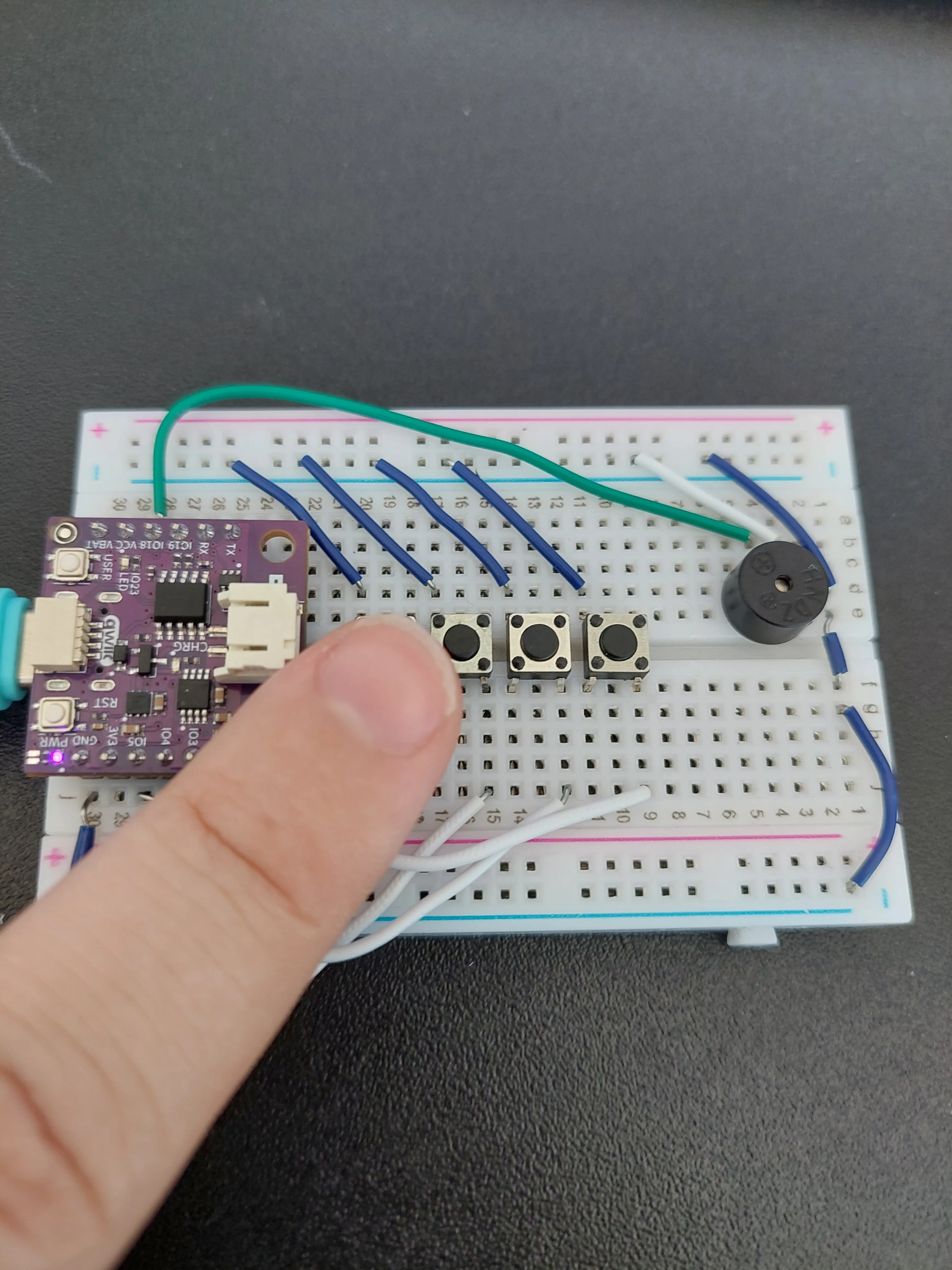
Things worth trying once it works:
- Hold two keys at once. Only the lower of the two sounds, because of the
else ifchain. - Play quickly. The short pause in
loop()means the board only looks at the keys 20 times a second, so very fast playing feels slightly soft-edged. - Change a frequency. Edit one of the
NOTE_values, upload again, and that key is retuned.
j30 out to the blue − rail, and the wire joining the two blue − rails. Without that second wire nothing on the a–e edge is grounded, so no button can pull its pin low and the buzzer has no return path. One key silent while the others work? That button's two wires are probably on the same side of the centre channel, or its legs landed in one row instead of two.IO2 reaches the button nearest the board and IO5 the furthest.Full example
Check out the full example code on the link below:
7.2_Mini_piano.ino
Project that creates a simple piano using 4 buttons and a passive buzzer. Each button produces a unique note.